PIC18F6525/6621/8525/8621
2
18.4.1
REGISTERS
18.4 I C Mode
The MSSP module has six registers for I2C operation.
These are:
The MSSP module in I2C mode fully implements all
master and slave functions (including general call
support) and provides interrupts on Start and Stop bits
in hardware to determine a free bus (multi-master func-
tion). The MSSP module implements the standard
mode specifications, as well as 7-bit and 10-bit
addressing.
• MSSP Control Register 1 (SSPCON1)
• MSSP Control Register 2 (SSPCON2)
• MSSP Status Register (SSPSTAT)
• Serial Receive/Transmit Buffer Register
(SSPBUF)
Two pins are used for data transfer:
• MSSP Shift Register (SSPSR) – Not directly
accessible
• Serial clock (SCL) – RC3/SCK/SCL
• Serial data (SDA) – RC4/SDI/SDA
• MSSP Address Register (SSPADD)
The user must configure these pins as inputs or outputs
through the TRISC<4:3> bits.
SSPCON1, SSPCON2 and SSPSTAT are the control
and status registers in I2C mode operation. The
SSPCON1 and SSPCON2 registers are readable and
writable. The lower 6 bits of the SSPSTAT are read-
only. The upper two bits of the SSPSTAT are read/
write.
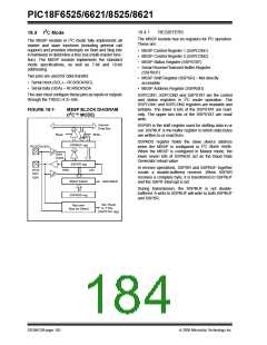
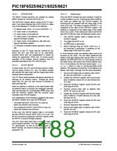
FIGURE 18-7:
MSSP BLOCK DIAGRAM
(I2C™ MODE)
Internal
Data Bus
SSPSR is the shift register used for shifting data in or
out. SSPBUF is the buffer register to which data bytes
are written to or read from.
Read
Write
SSPADD register holds the slave device address
when the MSSP is configured in I2C Slave mode.
When the MSSP is configured in Master mode, the
lower seven bits of SSPADD act as the Baud Rate
Generator reload value.
SSPBUF reg
RC3/SCK/SCL
Shift
Clock
SSPSR reg
In receive operations, SSPSR and SSPBUF together
create a double-buffered receiver. When SSPSR
receives a complete byte, it is transferred to SSPBUF
and the SSPIF interrupt is set.
RC4/
SDI/
SDA
MSb
LSb
Addr Match
Match Detect
SSPADD reg
During transmission, the SSPBUF is not double-
buffered. A write to SSPBUF will write to both SSPBUF
and SSPSR.
Set, Reset
S, P bits
(SSPSTAT reg)
Start and
Stop bit Detect
DS39612B-page 182
2005 Microchip Technology Inc.

 MICROCHIP [ MICROCHIP ]