PIC17C4X
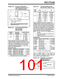
FIGURE 14-3: CRYSTAL OPERATION,
OVERTONE CRYSTALS (XT
OSC CONFIGURATION)
TABLE 14-3: CAPACITOR SELECTION
FOR CRYSTAL OSCILLATOR
Osc
Freq
C1
C2
C1
Type
OSC1
(1)
LF
32 kHz
100-150 pF
10-33 pF
10-33 pF
100-150 pF
10-33 pF
10-33 pF
1 MHz
2 MHz
SLEEP
C2
OSC2
XT
2 MHz
4 MHz
8 MHz
16 MHz
25 MHz
47-100 pF
15-68 pF
15-47 pF
TBD
47-100 pF
15-68 pF
15-47 pF
TBD
(2)
PIC17C42
0.1 µF
15-47 pF
15-47 pF
To filter the fundamental frequency
1
(3)
(3)
(3)
32 MHz
0
0
(2πf)2
=
LC2
Higher capacitance increases the stability of the
oscillator but also increases the start-up time and the
oscillator current. These values are for design guid-
ance only. RS may be required in XT mode to avoid
overdriving the crystals with low drive level specifica-
tion. Since each crystal has its own characteristics,
the user should consult the crystal manufacturer for
appropriate values for external components.
Note 1: For VDD > 4.5V, C1 = C2 ≈ 30 pF is recom-
mended.
Where f = tank circuit resonant frequency. This should be
midway between the fundamental and the 3rd overtone
frequencies of the crystal.
TABLE 14-2: CAPACITOR SELECTION
FOR CERAMIC
RESONATORS
Oscillator
Type
Resonator
Frequency
Capacitor Range
C1 = C2
2: RS of 330Ω is required for a capacitor com-
LF
455 kHz
2.0 MHz
15 - 68 pF
10 - 33 pF
bination of 15/15 pF.
3: Only the capacitance of the board was present.
XT
4.0 MHz
8.0 MHz
16.0 MHz
22 - 68 pF
33 - 100 pF
33 - 100 pF
Crystals Used:
32.768 kHz Epson C-001R32.768K-A ± 20 PPM
1.0 MHz
2.0 MHz
4.0 MHz
8.0 MHz
ECS-10-13-1
ECS-20-20-1
ECS-40-20-1
± 50 PPM
± 50 PPM
± 50 PPM
± 50 PPM
Higher capacitance increases the stability of the
oscillator but also increases the start-up time. These
values are for design guidance only. Since each reso-
nator has its own characteristics, the user should
consult the resonator manufacturer for appropriate
values of external components.
ECS ECS-80-S-4
ECS-80-18-1
16.0 MHz
25 MHz
32 MHz
ECS-160-20-1
CTS CTS25M
CRYSTEK HF-2
TBD
Resonators Used:
± 50 PPM
± 50 PPM
455 kHz
2.0 MHz
4.0 MHz
8.0 MHz
Panasonic EFO-A455K04B
Murata Erie CSA2.00MG
Murata Erie CSA4.00MG
Murata Erie CSA8.00MT
± 0.3%
± 0.5%
± 0.5%
± 0.5%
± 0.5%
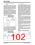
14.2.3 EXTERNAL CLOCK OSCILLATOR
In the EC oscillator mode, the OSC1 input can be
driven by CMOS drivers. In this mode, the
OSC1/CLKIN pin is hi-impedance and the OSC2/CLK-
OUT pin is the CLKOUT output (4 TOSC).
16.0 MHz Murata Erie CSA16.00MX
Resonators used did not have built-in capacitors.
FIGURE 14-4: EXTERNAL CLOCK INPUT
OPERATION (EC OSC
CONFIGURATION)
OSC1
OSC2
Clock from
ext. system
PIC17CXX
CLKOUT
(FOSC/4)
1996 Microchip Technology Inc.
DS30412C-page 101

 MICROCHIP [ MICROCHIP ]