PIC17C4X
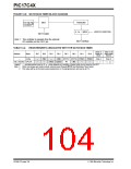
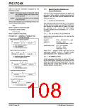
FIGURE 14-8: WATCHDOG TIMER BLOCK DIAGRAM
Postscaler
On-chip RC
Oscillator
WDT
(1)
WDTPS1:WDTPS0
4 - to - 1 MUX
WDT Overflow
WDT Enable
Note 1: This oscillator is separate from the external
RC oscillator on the OSC1 pin.
TABLE 14-4: REGISTERS/BITS ASSOCIATED WITH THE WATCHDOG TIMER
Value on
Power-on
Reset
Value on all
other resets
(Note1)
Address
Name
Bit 7
Bit 6
Bit 5
Bit 4
Bit 3
Bit 2
Bit 1
Bit 0
—
Config
—
—
PM1
—
—
PM0
WDTPS1 WDTPS0 FOSC1
TO PD
FOSC0
—
(Note 2)
(Note 2)
06h, Unbanked CPUSTA
STKAV
GLINTD
—
--11 11-- --11 qq--
Legend: -= unimplemented read as '0', q- value depends on condition, shaded cells are not used by the WDT.
Note 1: Other (non power-up) resets include: external reset through MCLR and Watchdog Timer Reset.
2: This value will be as the device was programmed, or if unprogrammed, will read as all '1's.
DS30412C-page 104
1996 Microchip Technology Inc.

 MICROCHIP [ MICROCHIP ]