PIC17C4X
14.1
Configuration Bits
14.2
Oscillator Configurations
The PIC17CXX has up to seven configuration locations
(Table 14-1). These locations can be programmed
(read as '0') or left unprogrammed (read as '1') to select
various device configurations. Any write to a configura-
tion location, regardless of the data, will program that
configuration bit. A TABLWT instruction is required to
write to program memory locations. The configuration
bits can be read by using the TABLRD instructions.
Reading any configuration location between FE00h
and FE07h will read the low byte of the configuration
word (Figure 14-1) into the TABLATL register. The TAB-
LATH register will be FFh. Reading a configuration
location between FE08h and FE0Fh will read the high
byte of the configuration word into the TABLATL regis-
ter. The TABLATH register will be FFh.
14.2.1
OSCILLATOR TYPES
The PIC17CXX can be operated in four different oscil-
lator modes. The user can program two configuration
bits (FOSC1:FOSC0) to select one of these four
modes:
• LF:
• XT:
• EC:
• RC:
Low Power Crystal
Crystal/Resonator
External Clock Input
Resistor/Capacitor
14.2.2 CRYSTAL OSCILLATOR / CERAMIC
RESONATORS
In XT or LF modes, a crystal or ceramic resonator is
connected to the OSC1/CLKIN and OSC2/CLKOUT
pins to establish oscillation (Figure 14-2). The
PIC17CXX Oscillator design requires the use of a par-
allel cut crystal. Use of a series cut crystal may give a
frequency out of the crystal manufacturers specifica-
tions.
Addresses FE00h thorough FE0Fh are only in the pro-
gram memory space for microcontroller and code pro-
tected microcontroller modes. A device programmer
will be able to read the configuration word in any pro-
cessor mode. See programming specifications for more
detail.
For frequencies above 20 MHz, it is common for the
crystal to be an overtone mode crystal. Use of overtone
mode crystals require a tank circuit to attenuate the
gain at the fundamental frequency. Figure 14-3 shows
an example of this.
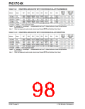
TABLE 14-1: CONFIGURATION
LOCATIONS
Bit
Address
FOSC0
FOSC1
WDTPS0
WDTPS1
PM0
FE00h
FE01h
FE02h
FE03h
FE04h
FE06h
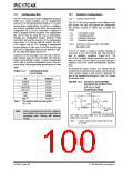
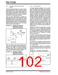
FIGURE 14-2: CRYSTAL OR CERAMIC
RESONATOR OPERATION
(XT OR LF OSC
CONFIGURATION)
OSC1
PM1
C1
(1)
(1)
PM2
FE0Fh
XTAL
SLEEP
Note 1: This location does not exist on the
PIC17C42.
RF
OSC2
Note1
To internal
logic
C2
Note: When programming the desired configura-
tion locations, they must be programmed in
ascending order. Starting with address
FE00h.
PIC17CXX
See Table 14-2 and Table 14-3 for recommended
values of C1 and C2.
Note 1: A series resistor may be required for AT strip
cut crystals.
DS30412C-page 100
1996 Microchip Technology Inc.

 MICROCHIP [ MICROCHIP ]