PIC17C75X
Table 18-2 lists the instructions recognized by the
MPASM assembler.
18.1
Special Function Registers as
Source/Destination
Note 1: Any unused opcode is Reserved. Use of
any reserved opcode may cause unex-
pected operation.
The PIC17C75X’s orthogonal instruction set allows
read and write of all file registers, including special
function registers. There are some special situations
the user should be aware of:
All instruction examples use the following format to rep-
resent a hexadecimal number:
18.1.1 ALUSTA AS DESTINATION
0xhh
If an instruction writes to ALUSTA, the Z, C, DC and OV
bits may be set or cleared as a result of the instruction
and overwrite the original data bits written. For exam-
where h signifies a hexadecimal digit.
To represent a binary number:
0000 0100b
ple, executing CLRF
ALUSTA will clear register
ALUSTA, and then set the Z bit leaving 0000 0100b
in the register.
where b signifies a binary string.
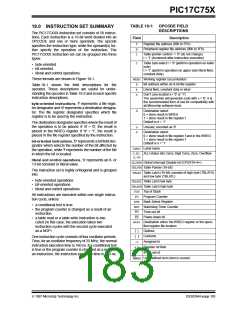
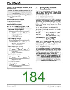
FIGURE 18-1: GENERAL FORMAT FOR
INSTRUCTIONS
18.1.2 PCL AS SOURCE OR DESTINATION
Byte-oriented file register operations
Read, write or read-modify-write on PCL may have the
following results:
15
9
8
7
0
OPCODE
d
f (FILE #)
Read PC:
PCH → PCLATH; PCL → dest
d = 0 for destination WREG
d = 1 for destination f
f = 8-bit file register address
Write PCL:
PCLATH → PCH;
8-bit destination value → PCL
Read-Modify-Write: PCL→ ALU operand
PCLATH → PCH;
Byte to Byte move operations
15 13 12
OPCODE p (FILE #)
8
7
0
0
8-bit result → PCL
f (FILE #)
Where PCH = program counter high byte (not an
addressable register), PCLATH = Program counter
high holding latch, dest = destination, WREG or f.
p = peripheral register file address
f = 8-bit file register address
18.1.3 BIT MANIPULATION
Bit-oriented file register operations
15 11 10
All bit manipulation instructions are done by first read-
ing the entire register, operating on the selected bit and
writing the result back (read-modify-write (R-M-W)).
The user should keep this in mind when operating on
some special function registers, such as ports.
8
7
OPCODE
b (BIT #)
f (FILE #)
b = 3-bit address
f = 8-bit file register address
Literal and control operations
15
Note: Status bits that are manipulated by the
device (including the Interrupt flag bits) are
set or cleared in the Q1 cycle. So there is
no issue on doing R-M-W instructions on
registers which contain these bits
8
7
0
0
OPCODE
k (literal)
k = 8-bit immediate value
CALL and GOTO operations
15 13 12
OPCODE
k (literal)
k = 13-bit immediate value
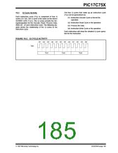
DS30264A-page 184
1997 Microchip Technology Inc.

 MICROCHIP [ MICROCHIP ]