PIC16F87/88
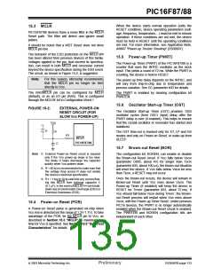
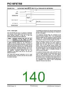
15.8 Time-out Sequence
15.9 Power Control/Status Register
(PCON)
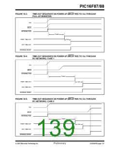
On power-up, the time-out sequence is as follows: the
PWRT delay starts (if enabled) when a POR occurs.
Then, OST starts counting 1024 oscillator cycles when
PWRT ends (LP, XT, HS). When the OST ends, the
device comes out of RESET.
The Power Control/Status Register, PCON, has two
bits to indicate the type of RESET that last occurred.
Bit0 is Brown-out Reset Status bit, BOR. Bit BOR is
unknown on a Power-on Reset. It must then be set by
the user and checked on subsequent RESETS to see
if bit BOR cleared, indicating a Brown-out Reset
occurred. When the Brown-out Reset is disabled, the
state of the BOR bit is unpredictable.
If MCLR is kept low long enough, all delays will expire.
Bringing MCLR high will begin execution immediately.
This is useful for testing purposes, or to synchronize
more than one PIC16F87/88 device operating in
parallel.
Bit1 is POR (Power-on Reset Status bit). It is cleared on
a Power-on Reset and unaffected otherwise. The user
must set this bit following a Power-on Reset.
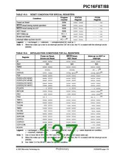
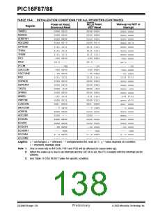
Table 15-3 shows the RESET conditions for the
STATUS, PCON and PC registers, while Table 15-4
shows the RESET conditions for all the registers.
TABLE 15-1: TIME-OUT IN VARIOUS SITUATIONS
Power-up
PWRTE = 0
Brown-out Reset
Oscillator
Configuration
Wake-up from
SLEEP
PWRTE = 1
1024 • TOSC
5-10 µs(1)
—
PWRTE = 0
PWRTE = 1
1024 • TOSC
5-10 µs(1)
—
XT, HS, LP
EXTRC, INTRC
T1OSC
TPWRT + 1024 • TOSC
TPWRT + 1024 • TOSC
1024 • TOSC
5-10 µs(1)
5-10 µs(1)
TPWRT
—
TPWRT
—
Note 1: CPU start-up is always invoked on POR, BOR and wake-up from SLEEP. The 5 µs-10 µs delay is based on
a 1 MHz system clock.
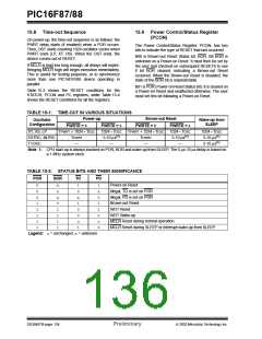
TABLE 15-2: STATUS BITS AND THEIR SIGNIFICANCE
POR
BOR
TO
PD
0
0
0
1
1
1
1
1
x
x
x
0
1
1
1
1
1
0
x
1
0
0
u
1
1
x
0
1
1
0
u
0
Power-on Reset
Illegal, TO is set on POR
Illegal, PD is set on POR
Brown-out Reset
WDT Reset
WDT Wake-up
MCLR Reset during normal operation
MCLR Reset during SLEEP or interrupt wake-up from SLEEP
Legend: u= unchanged, x= unknown
DS30487B-page 134
Preliminary
2003 Microchip Technology Inc.

 MICROCHIP [ MICROCHIP ]