PIC16F87/88
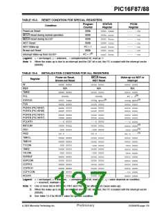
Some registers are not affected in any RESET condi-
tion. Their status is unknown on POR and unchanged
in any other RESET. Most other registers are reset to a
“RESET state” on Power-on Reset (POR), on the
MCLR and WDT Reset, on MCLR Reset during
SLEEP, and Brown-out Reset (BOR). They are not
affected by a WDT wake-up, which is viewed as the
resumption of normal operation. The TO and PD bits
are set or cleared differently in different RESET situa-
tions, as indicated in Table 15-3. These bits are used in
software to determine the nature of the RESET. Upon
a POR, BOR, or wake-up from SLEEP, the CPU
requires approximately 5-10 µs to become ready for
code execution. This delay runs in parallel with any
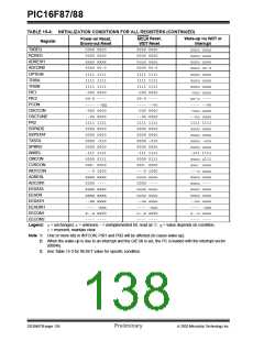
other timers. See Table 15-4 for a full description of
RESET states of all registers.
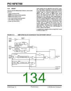
15.2 RESET
The PIC16F87/88 differentiates between various kinds
of RESET:
• Power-on Reset (POR)
• MCLR Reset during normal operation
• MCLR Reset during SLEEP
• WDT Reset during normal operation
• WDT Wake-up during SLEEP
• Brown-out Reset (BOR)
A simplified block diagram of the on-chip RESET circuit
is shown in Figure 15-1.
FIGURE 15-1:
SIMPLIFIED BLOCK DIAGRAM OF ON-CHIP RESET CIRCUIT
External
RESET
MCLR
SLEEP
WDT
WDT
Module
Time-out
Reset
VDD Rise
Detect
Power-on Reset
VDD
Brown-out
Reset
S
BOREN
OST/PWRT
OST
10-bit Ripple Counter
Chip_Reset
R
Q
OSC1
PWRT
11-bit Ripple Counter
INTRC
31.25 kHz
Enable PWRT
Enable OST
DS30487B-page 132
Preliminary
2003 Microchip Technology Inc.

 MICROCHIP [ MICROCHIP ]