PIC16F716
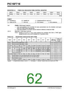
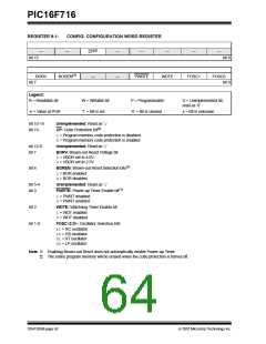
REGISTER 9-1:
CONFIG: CONFIGURATION WORD REGISTER
CP(2)
—
—
—
—
—
—
—
bit 15
bit 8
BORV
bit 7
BOREN(1)
—
—
PWRTE
WDTE
FOSC1
FOSC0
bit 0
Legend:
R = Readable bit
W = Writable bit
‘1’ = Bit is set
P = Programmable’
‘0’ = Bit is cleared
U = Unimplemented bit,
read as ‘0’
-n = Value at POR
x = Bit is unknown
bit 15-14
bit 13
Unimplemented: Read as ‘1’
CP: Code Protection bit(2)
1= Program memory code protection is disabled
0= Program memory code protection is enabled
bit 12-8
bit 7
Unimplemented: Read as ‘1’
BORV: Brown-out Reset Voltage bit
1= VBOR set to 4.0V
0= VBOR set to 2.5V
bit 6
BOREN: Brown-out Reset Selection bits(1)
1= BOR enabled
0= BOR disabled
bit 5-4
bit 3
Unimplemented: Read as ‘1’
PWRTE: Power-up Timer Enable bit(1)
1= PWRT disabled
0= PWRT enabled
bit 2
WDTE: Watchdog Timer Enable bit
1= WDT enabled
0= WDT disabled
bit 1-0
FOSC<2:0>: Oscillator Selection bits
11= RC oscillator
10= HS oscillator
01= XT oscillator
00= LP oscillator
Note 1: Enabling Brown-out Reset does not automatically enable Power-up Timer.
2: The entire program memory will be erased when the code protection is turned off.
DS41206B-page 62
© 2007 Microchip Technology Inc.

 MICROCHIP [ MICROCHIP ]