PIC16F716
A simplified block diagram of the On-chip Reset circuit
is shown in Figure 9-5.
The PIC® microcontrollers have an MCLR noise filter in
the MCLR Reset path. The filter will detect and ignore
small pulses.
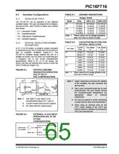
9.2.3
RC OSCILLATOR
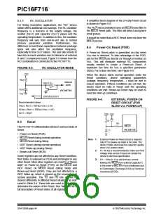
For timing insensitive applications, the “RC” device
option offers additional cost savings. The RC oscillator
frequency is a function of the supply voltage, the
resistor (REXT) and capacitor (CEXT) values and the
operating temperature. In addition to this, the oscillator
frequency will vary from unit-to-unit due to normal
process parameter variation. Furthermore, the
difference in lead frame capacitance between package
types will also affect the oscillation frequency,
especially for low CEXT values. The user also needs to
take into account variation due to tolerance of external
R and C components used. Figure 9-3 shows how the
R/C combination is connected to the PIC16F716.
It should be noted that a WDT Reset does not drive the
MCLR pin low.
9.4
Power-On Reset (POR)
A Power-on Reset pulse is generated on-chip when
VDD rise is detected. To take advantage of the POR,
just tie the MCLR pin directly (or through a resistor) to
VDD. This will eliminate external RC components
usually needed to create a Power-on Reset. A
maximum rise time for VDD is specified (parameter
D004). For a slow rise time, see Figure 9-4.
FIGURE 9-3:
RC OSCILLATOR MODE
VDD
When the device starts normal operation (exits the
Reset condition), device operating parameters
(voltage, frequency, temperature,...) must be met to
ensure operation. If these conditions are not met, the
device must be held in Reset until the operating
conditions are met. Brown-out Reset may be used to
meet the start-up conditions.
REXT
Internal
OSC1
clock
CEXT
VSS
PIC16F716
OSC2/CLKOUT
FOSC/4
Recommended values:
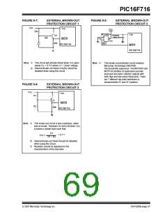
FIGURE 9-4:
EXTERNAL POWER-ON
RESET CIRCUIT (FOR
SLOW VDD POWER-UP)
3 kΩ ≤ REXT ≤ 100 kΩ (VDD ≥ 3.0V)
10 kΩ ≤ REXT ≤ 100 kΩ (VDD ≥ 3.0V)
CEXT > 20 pF
VDD VDD
R
9.3
Reset
R1
MCLR
The PIC16F716 differentiates between various kinds of
Reset:
PIC16F716
C
• Power-on Reset (POR)
• MCLR Reset during normal operation
• MCLR Reset during Sleep
Note 1: External Power-on Reset circuit is required
only if VDD power-up slope is too slow. The
diode D helps discharge the capacitor quickly
when VDD powers down.
• WDT Reset (during normal operation)
• WDT Wake-up (during Sleep)
• Brown-out Reset (BOR)
2: R < 40 kΩ is recommended to make sure that
voltage drop across R does not violate the
device’s electrical specification.
Some registers are not affected in any Reset condition;
their status is unknown on POR and unchanged in any
other Reset. Most other registers are reset to a “Reset
state” on Power-on Reset (POR), on the MCLR and
WDT Reset, on MCLR Reset during Sleep and
Brown-out Reset (BOR). They are not affected by a
WDT Wake-up, which is viewed as the resumption of
normal operation. The TO and PD bits are set or
cleared differently in different Reset situations as indi-
cated in Table 9-4. These bits are used in software to
determine the nature of the Reset. See Table 9-6 for a
full description of Reset states of all registers.
3: R1 = 100Ω to 1 kΩ will limit any current
flowing into MCLR from external capacitor C
in the event of MCLR/VPP pin breakdown due
to Electrostatic Discharge (ESD) or Electrical
Overstress (EOS).
DS41206B-page 64
© 2007 Microchip Technology Inc.

 MICROCHIP [ MICROCHIP ]