PIC16F716
5.8
ECCP Capture/Compare Time
Base
5.9
ECCP Special Event Trigger
If a ECCP is configured to trigger a special event, the
trigger will clear the TMR1H:TMR1L register pair. This
special event does not cause a Timer1 interrupt. The
ECCP module may still be configured to generate a
ECCP interrupt.
The ECCP module uses the TMR1H:TMR1L register
pair as the time base when operating in Capture or
Compare mode.
In Capture mode, the value in the TMR1H:TMR1L
register pair is copied into the CCPR1H:CCPR1L
register pair on a configured event.
In this mode of operation, the CCPR1H:CCPR1L regis-
ter pair effectively becomes the period register for
Timer1.
In Compare mode, an event is triggered when the value
CCPR1H:CCPR1L register pair matches the value in
the TMR1H:TMR1L register pair. This event can be a
Special Event Trigger.
Timer1 should be synchronized to the FOSC to utilize
the Special Event Trigger. Asynchronous operation of
Timer1 can cause a Special Event Trigger to be
missed.
For more information, see Section 8.0 “Enhanced
Capture/Compare/PWM Module”.
In the event that a write to TMR1H or TMR1L coincides
with a Special Event Trigger from the ECCP, the write
will take precedence.
For more information, see Section 8.0 “Enhanced
Capture/Compare/PWM Module”.
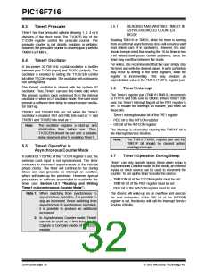
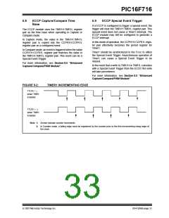
FIGURE 5-2:
TIMER1 INCREMENTING EDGE
T1CKI = 1
when TMR1
Enabled
T1CKI = 0
when TMR1
Enabled
Note 1: Arrows indicate counter increments.
2: In Counter mode, a falling edge must be registered by the counter prior to the first incrementing rising edge of
the clock.
© 2007 Microchip Technology Inc.
DS41206B-page 31

 MICROCHIP [ MICROCHIP ]