PIC16F716
5.5.1
READING AND WRITING TIMER1 IN
ASYNCHRONOUS COUNTER
MODE
5.3
Timer1 Prescaler
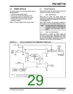
Timer1 has four prescaler options allowing 1, 2, 4 or 8
divisions of the clock input. The T1CKPS bits of the
T1CON register control the prescale counter. The
prescale counter is not directly readable or writable;
however, the prescaler counter is cleared upon a write to
TMR1H or TMR1L.
Reading TMR1H or TMR1L while the timer is running
from an external asynchronous clock will ensure a valid
read (taken care of in hardware). However, the user
should keep in mind that reading the 16-bit timer in two
8-bit values itself poses certain problems, since the
timer may overflow between the reads.
5.4
Timer1 Oscillator
For writes, it is recommended that the user simply stop
the timer and write the desired values. A write contention
may occur by writing to the timer registers, while the
register is incrementing. This may produce an
unpredictable value in the TMR1H:TMR1L register pair.
A low-power 32.768 kHz crystal oscillator is built-in
between pins T1OSI (input) and T1OSO (output). The
oscillator is enabled by setting the T1OSCEN control
bit of the T1CON register. The oscillator will continue to
run during Sleep.
The Timer1 oscillator is shared with the system LP
oscillator. Thus, Timer1 can use this mode only when
the primary system clock is derived from the internal
oscillator or when in LP oscillator mode. The user must
provide a software time delay to ensure proper oscilla-
tor start-up.
5.6
Timer1 Interrupt
The Timer1 register pair (TMR1H:TMR1L) increments
to FFFFh and rolls over to 0000h. When Timer1 rolls
over, the Timer1 interrupt flag bit of the PIR1 register is
set. To enable the interrupt on rollover, you must set
these bits:
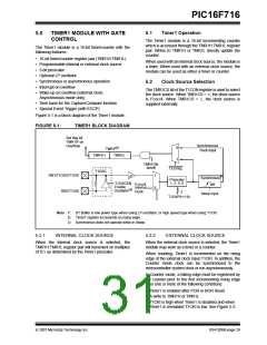
TRISB1 and TRISB2 bits are set when the Timer1
oscillator is enabled. RB1 and RB2 bits read as ‘0’ and
TRISB1 and TRISB2 bits read as ‘1’.
• Timer1 interrupt enable bit of the PIE1 register
• PEIE bit of the INTCON register
• GIE bit of the INTCON register
Note:
The oscillator requires a start-up and
stabilization time before use. Thus,
T1OSCEN should be set and a suitable
delay observed prior to enabling Timer1.
The interrupt is cleared by clearing the TMR1IF bit in
the Interrupt Service Routine.
Note:
The TMR1H:TMR1L register pair and the
TMR1IF bit should be cleared before
enabling interrupts.
5.5
Timer1 Operation in
Asynchronous Counter Mode
5.7
Timer1 Operation During Sleep
If control bit T1SYNC of the T1CON register is set, the
external clock input is not synchronized. The timer
continues to increment asynchronous to the internal
phase clocks. The timer will continue to run during
Sleep and can generate an interrupt on overflow,
which will wake-up the processor. However, special
precautions in software are needed to read/write the
timer (see Section 5.5.1 “Reading and Writing
Timer1 in Asynchronous Counter Mode”).
Timer1 can only operate during Sleep when setup in
Asynchronous Counter mode. In this mode, an external
crystal or clock source can be used to increment the
counter. To set up the timer to wake the device:
• TMR1ON bit of the T1CON register must be set
• TMR1IE bit of the PIE1 register must be set
• PEIE bit of the INTCON register must be set
Note 1: When switching from synchronous to
asynchronous operation, it is possible to
skip an increment. When switching from
asynchronous to synchronous operation,
it is possible to produce an additional
increment.
The device will wake-up on an overflow and execute
the next instruction. If the GIE bit of the INTCON
register is set, the device will call the Interrupt Service
Routine (0004h).
2: In Asynchronous Counter mode, Timer1
can not be used as a time base for the
Capture or Compare modes of the ECCP
module.
DS41206B-page 30
© 2007 Microchip Technology Inc.

 MICROCHIP [ MICROCHIP ]