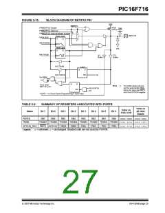
PIC16F716
5.1
Timer1 Operation
5.0
TIMER1 MODULE WITH GATE
CONTROL
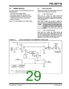
The Timer1 module is a 16-bit incrementing counter
which is accessed through the TMR1H:TMR1L register
pair. Writes to TMR1H or TMR1L directly update the
counter.
The Timer1 module is a 16-bit timer/counter with the
following features:
• 16-bit timer/counter register pair (TMR1H:TMR1L)
• Programmable internal or external clock source
• 3-bit prescaler
When used with an internal clock source, the module is
a timer. When used with an external clock source, the
module can be used as either a timer or counter.
• Optional LP oscillator
• Synchronous or asynchronous operation
• Interrupt on overflow
5.2
Clock Source Selection
The TMR1CS bit of the T1CON register is used to select
the clock source. When TMR1CS = 0, the clock source
is FOSC/4. When TMR1CS = 1, the clock source is
supplied externally.
• Wake-up on overflow (external clock,
Asynchronous mode only)
• Time base for the Capture/Compare function
• Special Event Trigger (with ECCP)
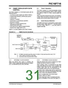
Figure 5-1 is a block diagram of the Timer1 module.
FIGURE 5-1:
TIMER1 BLOCK DIAGRAM
Set flag bit
TMR1IF on
Overflow
Synchronized
(2)
0
TMR1
clock input
TMR1L
TMR1H
1
TMR1ON
on/off
T1SYNC
T1OSC
RB1/T1OSO/T1CKI
1
(3)
Synchronize
det
Prescaler
1, 2, 4, 8
T1OSCEN
Enable
Oscillator
FOSC/4
Internal
Clock
0
(1)
RB2/T1OSI
2
Sleep input
T1CKPS<1:0>
Note 1: ST Buffer is low power type when using LP oscillator, or high speed type when using T1CKI.
2: Timer1 register increments on rising edge.
3: Synchronize does not operate while in Sleep.
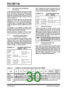
5.2.1
INTERNAL CLOCK SOURCE
5.2.2
EXTERNAL CLOCK SOURCE
When the internal clock source is selected, the
TMR1H:TMR1L register pair will increment on multiples
of TCY as determined by the Timer1 prescaler.
When the external clock source is selected, the Timer1
module may work as a timer or a counter.
When counting, Timer1 is incremented on the rising
edge of the external clock input T1CKI. In addition, the
Counter mode clock can be synchronized to the
microcontroller system clock or run asynchronously.
In Counter mode, a falling edge must be registered by
the counter prior to the first incrementing rising edge
after one or more of the following conditions:
• Timer1 is enabled after POR or BOR Reset
• A write to TMR1H or TMR1L
• T1CKI is high when Timer1 is disabled and when
Timer1 is reenabled T1CKI is low. See Figure 5-2.
© 2007 Microchip Technology Inc.
DS41206B-page 29

 MICROCHIP [ MICROCHIP ]