PIC16F716
The TMR2 and PR2 registers are both fully readable
and writable. On any Reset, the TMR2 register is set to
00h and the PR2 register is set to FFh.
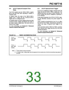
6.0
TIMER2 MODULE
The Timer2 module is an 8-bit timer with the following
features:
Timer2 is turned on by setting the TMR2ON bit in the
T2CON register to a ‘1’. Timer2 is turned off by clearing
the TMR2ON bit to a ‘0’.
• 8-bit timer register (TMR2)
• 8-bit period register (PR2)
• Interrupt on TMR2 match with PR2
• Software programmable prescaler (1:1, 1:4, 1:16)
• Software programmable postscaler (1:1 to 1:16)
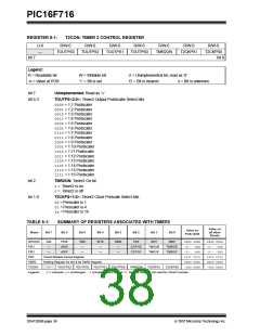
The Timer2 prescaler is controlled by the T2CKPS bits
in the T2CON register. The Timer2 postscaler is
controlled by the TOUTPS bits in the T2CON register.
The prescaler and postscaler counters are cleared
when:
See Figure 6-1 for a block diagram of Timer2.
• A write to TMR2 occurs.
• A write to T2CON occurs.
6.1
Timer2 Operation
The clock input to the Timer2 module is the system
instruction clock (FOSC/4). The clock is fed into the
Timer2 prescaler, which has prescale options of 1:1,
1:4 or 1:16. The output of the prescaler is then used to
increment the TMR2 register.
• Any device Reset occurs (Power-on Reset, MCLR
Reset, Watchdog Timer Reset, or Brown-out
Reset).
Note:
TMR2 is not cleared when T2CON is
written.
The values of TMR2 and PR2 are constantly compared
to determine when they match. TMR2 will increment
from 00h until it matches the value in PR2. When a
match occurs, two things happen:
• TMR2 is reset to 00h on the next increment cycle
• The Timer2 postscaler is incremented
The match output of the Timer2/PR2 comparator is
then fed into the Timer2 postscaler. The postscaler has
postscale options of 1:1 to 1:16 inclusive. The output of
the Timer2 postscaler is used to set the TMR2IF
interrupt flag bit in the PIR2 register.
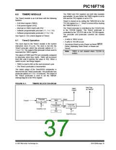
FIGURE 6-1:
TIMER2 BLOCK DIAGRAM
Sets Flag
bit TMR2IF
TMR2
Output
Prescaler
Reset
EQ
TMR2
FOSC/4
1:1, 1:4, 1:16
Postscaler
1:1 to 1:16
2
Comparator
PR2
T2CKPS<1:0>
4
TOUTPS<3:0>
© 2007 Microchip Technology Inc.
DS41206B-page 35

 MICROCHIP [ MICROCHIP ]