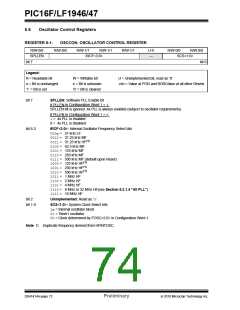
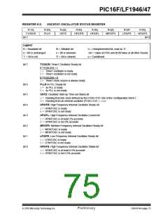
PIC16F/LF1946/47
6.1
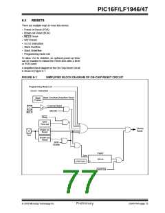
Power-on Reset (POR)
6.2
Brown-Out Reset (BOR)
The POR circuit holds the device in Reset until VDD has
reached an acceptable level for minimum operation.
Slow rising VDD, fast operating speeds or analog
performance may require greater than minimum VDD.
The PWRT, BOR or MCLR features can be used to
extend the start-up period until all device operation
conditions have been met.
The BOR circuit holds the device in Reset when Vdd
reaches a selectable minimum level. Between the
POR and BOR, complete voltage range coverage for
execution protection can be implemented.
The Brown-out Reset module has four operating
modes controlled by the BOREN<1:0> bits in Configu-
ration Word 1. The four operating modes are:
• BOR is always on
6.1.1
POWER-UP TIMER (PWRT)
• BOR is off when in Sleep
• BOR is controlled by software
• BOR is always off
The Power-up Timer provides a nominal 64 ms time-
out on POR or Brown-out Reset.
The device is held in Reset as long as PWRT is active.
The PWRT delay allows additional time for the VDD to
rise to an acceptable level. The Power-up Timer is
enabled by clearing the PWRTE bit in Configuration
Word 1.
Refer to Table 6-3 for more information.
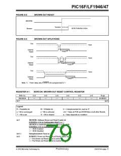
The Brown-out Reset voltage level is selectable by
configuring the BORV bit in Configuration Word 2.
A VDD noise rejection filter prevents the BOR from trig-
gering on small events. If VDD falls below VBOR for a
duration greater than parameter TBORDC, the device
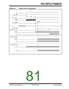
will reset. See Figure 6-3 for more information.
The Power-up Timer starts after the release of the POR
and BOR.
For additional information, refer to Application Note
AN607, “Power-up Trouble Shooting” (DS00607).
TABLE 6-1:
BOR OPERATING MODES
Device
Device
BOREN
Config bits
Operation upon
SBOREN
Device Mode
BOR Mode
Operation upon
release of POR
wake-up from
Sleep
BOR_ON (11)
X
X
X
1
0
X
X
Awake
Sleep
X
Active
Active
Waits for BOR ready(1)
BOR_NSLEEP (10)
BOR_NSLEEP (10)
BOR_SBOREN (01)
BOR_SBOREN (01)
BOR_OFF (00)
Waits for BOR ready
Disabled
Active
Begins immediately
Begins immediately
Begins immediately
X
Disabled
Disabled
X
Note 1: Even though this case specifically waits for the BOR, the BOR is already operating, so there is no delay in
start-up.
6.2.1
BOR IS ALWAYS ON
6.2.3
BOR CONTROLLED BY SOFTWARE
When the BOREN bits of Configuration Word 1 are set
to ‘11’, the BOR is always on. The device start-up will
be delayed until the BOR is ready and VDD is higher
than the BOR threshold.
When the BOREN bits of Configuration Word 1 are set
to ‘01’, the BOR is controlled by the SBOREN bit of the
BORCON register. The device start-up is not delayed
by the BOR ready condition or the VDD level.
BOR protection is active during Sleep. The BOR does
not delay wake-up from Sleep.
BOR protection begins as soon as the BOR circuit is
ready. The status of the BOR circuit is reflected in the
BORRDY bit of the BORCON register.
6.2.2
BOR IS OFF IN SLEEP
BOR protection is unchanged by Sleep.
When the BOREN bits of Configuration Word 1 are set
to ‘10’, the BOR is on, except in Sleep. The device
start-up will be delayed until the BOR is ready and VDD
is higher than the BOR threshold.
BOR protection is not active during Sleep. The device
wake-up will be delayed until the BOR is ready.
DS41414A-page 76
Preliminary
2010 Microchip Technology Inc.

 MICROCHIP [ MICROCHIP ]