PIC16F/LF1946/47
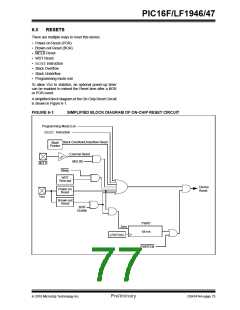
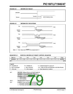
FIGURE 6-2:
BROWN-OUT READY
SBOREN
TBORRDY
BOR Protection Active
BORRDY
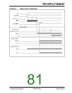
FIGURE 6-3:
BROWN-OUT SITUATIONS
VDD
VBOR
Internal
Reset
(1)
TPWRT
VDD
VBOR
Internal
Reset
< TPWRT
(1)
TPWRT
VDD
VBOR
Internal
Reset
(1)
TPWRT
Note 1: TPWRT delay only if PWRTE bit is programmed to ‘0’.
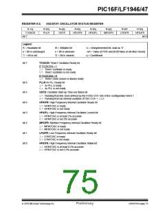
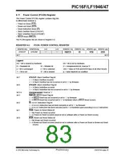
REGISTER 6-1:
BORCON: BROWN-OUT RESET CONTROL REGISTER
R/W-1/u
SBOREN
bit 7
U-0
—
U-0
—
U-0
—
U-0
—
U-0
—
U-0
R-q/u
—
BORRDY
bit 0
Legend:
R = Readable bit
u = Bit is unchanged
‘1’ = Bit is set
W = Writable bit
x = Bit is unknown
‘0’ = Bit is cleared
U = Unimplemented bit, read as ‘0’
-n/n = Value at POR and BOR/Value at all other Resets
q = Value depends on condition
bit 7
SBOREN: Software Brown-out Reset Enable bit
If BOREN <1:0> in Configuration Word 1 01:
SBOREN is read/write, but has no effect on the BOR.
If BOREN <1:0> in Configuration Word 1 = 01:
1= BOR Enabled
0= BOR Disabled
bit 6-1
bit 0
Unimplemented: Read as ‘0’
BORRDY: Brown-out Reset Circuit Ready Status bit
1= The Brown-out Reset circuit is active
0= The Brown-out Reset circuit is inactive
2010 Microchip Technology Inc.
Preliminary
DS41414A-page 77

 MICROCHIP [ MICROCHIP ]