PIC16F/LF1946/47
6.3
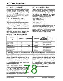
MCLR
6.7
Programming Mode Exit
The MCLR is an optional external input that can reset
the device. The MCLR function is controlled by the
MCLRE bit of Configuration Word 1 and the LVP bit of
Configuration Word 2 (Table 6-2).
Upon exit of Programming mode, the device will
behave as if a POR had just occurred.
6.8
Power-Up Timer
The Power-up Timer optionally delays device execution
after a BOR or POR event. This timer is typically used to
allow VDD to stabilize before allowing the device to start
running.
TABLE 6-2:
MCLRE
MCLR CONFIGURATION
LVP
MCLR
0
1
x
0
0
1
Disabled
Enabled
Enabled
The Power-up Timer is controlled by the PWRTE bit of
Configuration Word 1.
6.9
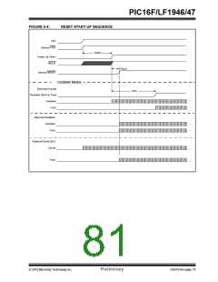
Start-up Sequence
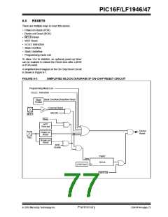
6.3.1
MCLR ENABLED
Upon the release of a POR or BOR, the following must
occur before the device will begin executing:
When MCLR is enabled and the pin is held low, the
device is held in Reset. The MCLR pin is connected to
VDD through an internal weak pull-up.
1. Power-up Timer runs to completion (if enabled).
2. Oscillator start-up timer runs to completion (if
required for oscillator source).
The device has a noise filter in the MCLR Reset path.
The filter will detect and ignore small pulses.
3. MCLR must be released (if enabled).
Note:
A Reset does not drive the MCLR pin low.
The total time-out will vary based on oscillator configu-
ration and Power-up Timer configuration. See
Section 5.0 “Oscillator Module (With Fail-Safe
Clock Monitor)” for more information.
6.3.2
MCLR DISABLED
When MCLR is disabled, the pin functions as a general
purpose input and the internal weak pull-up is under
software control. See Section 12.6 “PORTE
Registers” for more information.
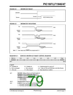
The Power-up Timer and oscillator start-up timer run
independently of MCLR Reset. If MCLR is kept low long
enough, the Power-up Timer and oscillator start-up
timer will expire. Upon bringing MCLR high, the device
will begin execution immediately (see Figure 6-4). This
is useful for testing purposes or to synchronize more
than one device operating in parallel.
6.4
Watchdog Timer (WDT) Reset
The Watchdog Timer generates a Reset if the firmware
does not issue a CLRWDTinstruction within the time-out
period. The TO and PD bits in the STATUS register are
changed to indicate the WDT Reset. See Section 10.0
“Watchdog Timer” for more information.
6.5
RESET Instruction
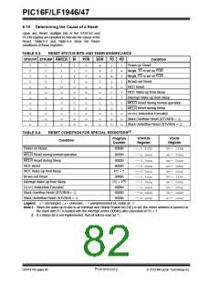
A RESETinstruction will cause a device Reset. The RI
bit in the PCON register will be set to ‘0’. See Table 6-4
for default conditions after a RESET instruction has
occurred.
6.6
Stack Overflow/Underflow Reset
The device can reset when the Stack Overflows or
Underflows. The STKOVF or STKUNF bits of the PCON
register indicate the Reset condition. These Resets are
enabled by setting the STVREN bit in Configuration Word
2. See Section 3.4.2 “Overflow/Underflow Reset” for
more information.
DS41414A-page 78
Preliminary
2010 Microchip Technology Inc.

 MICROCHIP [ MICROCHIP ]