PIC16F/LF1946/47
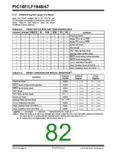
6.10 Determining the Cause of a Reset
Upon any Reset, multiple bits in the STATUS and
PCON register are updated to indicate the cause of the
Reset. Table 6-3 and Table 6-4 show the Reset
conditions of these registers.
TABLE 6-3:
RESET STATUS BITS AND THEIR SIGNIFICANCE
STKOVF STKUNF RMCLR
RI
POR
BOR
TO
PD
Condition
0
0
0
0
u
u
u
u
u
u
1
u
0
0
0
0
u
u
u
u
u
u
u
1
1
1
1
1
u
u
u
0
0
u
u
u
1
1
1
1
u
u
u
u
u
0
u
u
0
0
0
u
u
u
u
u
u
u
u
u
x
x
x
0
u
u
u
u
u
u
u
u
1
0
x
1
0
0
1
u
1
u
u
u
1
x
0
1
u
0
0
u
0
u
u
u
Power-on Reset
Illegal, TO is set on POR
Illegal, PD is set on POR
Brown-out Reset
WDT Reset
WDT Wake-up from Sleep
Interrupt Wake-up from Sleep
MCLR Reset during normal operation
MCLR Reset during Sleep
RESETInstruction Executed
Stack Overflow Reset (STVREN = 1)
Stack Underflow Reset (STVREN = 1)
TABLE 6-4:
RESET CONDITION FOR SPECIAL REGISTERS(2)
Program
STATUS
Register
PCON
Register
Condition
Counter
Power-on Reset
0000h
---1 1000
---u uuuu
00-- 110x
uu-- 0uuu
MCLR Reset during normal operation
0000h
MCLR Reset during Sleep
WDT Reset
0000h
0000h
---1 0uuu
---0 uuuu
---0 0uuu
---1 1uuu
---1 0uuu
---u uuuu
---u uuuu
---u uuuu
uu-- 0uuu
uu-- uuuu
uu-- uuuu
00-- 11u0
uu-- uuuu
uu-- u0uu
1u-- uuuu
u1-- uuuu
WDT Wake-up from Sleep
Brown-out Reset
PC + 1
0000h
Interrupt Wake-up from Sleep
RESETInstruction Executed
Stack Overflow Reset (STVREN = 1)
Stack Underflow Reset (STVREN = 1)
PC + 1(1)
0000h
0000h
0000h
Legend: u= unchanged, x= unknown, -= unimplemented bit, reads as ‘0’.
Note 1: When the wake-up is due to an interrupt and Global Enable bit (GIE) is set, the return address is pushed on
the stack and PC is loaded with the interrupt vector (0004h) after execution of PC + 1.
2: If a Status bit is not implemented, that bit will be read as ‘0’.
DS41414A-page 80
Preliminary
2010 Microchip Technology Inc.

 MICROCHIP [ MICROCHIP ]