PIC16F/LF1946/47
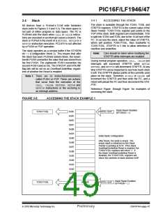
FIGURE 3-6:
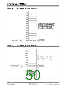
ACCESSING THE STACK EXAMPLE 2
0x0F
0x0E
0x0D
0x0C
0x0B
0x0A
0x09
0x08
0x07
0x06
0x05
0x04
0x03
0x02
0x01
0x00
This figure shows the stack configuration
after the first CALLor a single interrupt.
If a RETURN instruction is executed, the
return address will be placed in the
Program Counter and the Stack Pointer
decremented to the empty state (0x1F).
TOSH:TOSL
Return Address
STKPTR = 0x00
FIGURE 3-7:
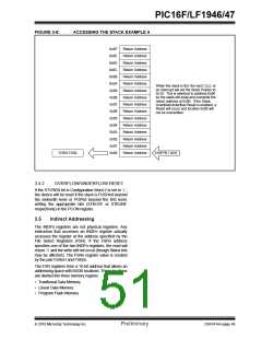
ACCESSING THE STACK EXAMPLE 3
0x0F
0x0E
0x0D
0x0C
0x0B
0x0A
0x09
0x08
0x07
After seven CALLs or six CALLs and an
interrupt, the stack looks like the figure
on the left. A series of RETURNinstructions
will repeatedly place the return addresses
into the Program Counter and pop the stack.
STKPTR = 0x06
TOSH:TOSL
0x06
0x05
0x04
0x03
0x02
0x01
0x00
Return Address
Return Address
Return Address
Return Address
Return Address
Return Address
Return Address
DS41414A-page 48
Preliminary
2010 Microchip Technology Inc.

 MICROCHIP [ MICROCHIP ]