PIC16F/LF1946/47
3.3.3
COMPUTED FUNCTION CALLS
3.3
PCL and PCLATH
A computed function CALLallows programs to maintain
tables of functions and provide another way to execute
state machines or look-up tables. When performing a
table read using a computed function CALL, care
should be exercised if the table location crosses a PCL
memory boundary (each 256-byte block).
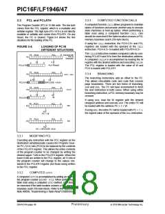
The Program Counter (PC) is 15 bits wide. The low byte
comes from the PCL register, which is a readable and
writable register. The high byte (PC<14:8>) is not directly
readable or writable and comes from PCLATH. On any
Reset, the PC is cleared. Figure 3-4 shows the five
situations for the loading of the PC.
If using the CALLinstruction, the PCH<2:0> and PCL
registers are loaded with the operand of the CALL
instruction. PCH<6:3> is loaded with PCLATH<6:3>.
FIGURE 3-4:
LOADING OF PC IN
DIFFERENT SITUATIONS
The CALLWinstruction enables computed calls by com-
bining PCLATH and W to form the destination address.
A computed CALLWis accomplished by loading the W
register with the desired address and executing CALLW.
The PCL register is loaded with the value of W and
PCH is loaded with PCLATH.
14
0
Instruction with
PCL as
Destination
PCH
PCL
PC
8
7
6
0
ALU Result
PCLATH
14
0
PCH
PCL
3.3.4
BRANCHING
GOTO, CALL
PC
The branching instructions add an offset to the PC.
This allows relocatable code and code that crosses
page boundaries. There are two forms of branching,
BRW and BRA. The PC will have incremented to fetch
the next instruction in both cases. When using either
branching instruction, a PCL memory boundary may be
crossed.
4
11
6
0
0
PCLATH
OPCODE <10:0>
14
0
PCH
PCL
CALLW
PC
7
8
6
W
PCLATH
If using BRW, load the W register with the desired
unsigned address and execute BRW. The entire PC will
be loaded with the address PC + 1 + W.
14
0
0
PCH
PCH
PCL
BRW
PC
If using BRA, the entire PC will be loaded with PC + 1 +,
the signed value of the operand of the BRAinstruction.
15
PC + W
14
PCL
BRA
PC
15
PC + OPCODE <8:0>
3.3.1
MODIFYING PCL
Executing any instruction with the PCL register as the
destination simultaneously causes the Program Coun-
ter PC<14:8> bits (PCH) to be replaced by the contents
of the PCLATH register. This allows the entire contents
of the program counter to be changed by writing the
desired upper 7 bits to the PCLATH register. When the
lower 8 bits are written to the PCL register, all 15 bits of
the program counter will change to the values con-
tained in the PCLATH register and those being written
to the PCL register.
3.3.2
COMPUTED GOTO
A computed GOTOis accomplished by adding an offset to
the program counter (ADDWF PCL). When performing a
table read using a computed GOTOmethod, care should
be exercised if the table location crosses a PCL memory
boundary (each 256-byte block). Refer to the Application
Note AN556, “Implementing a Table Read” (DS00556).
DS41414A-page 46
Preliminary
2010 Microchip Technology Inc.

 MICROCHIP [ MICROCHIP ]