PIC16F/LF1946/47
3.4.1
ACCESSING THE STACK
3.4
Stack
The stack is available through the TOSH, TOSL and
STKPTR registers. STKPTR is the current value of the
Stack Pointer. TOSH:TOSL register pair points to the
TOP of the stack. Both registers are read/writable. TOS
is split into TOSH and TOSL due to the 15-bit size of the
PC. To access the stack, adjust the value of STKPTR,
which will position TOSH:TOSL, then read/write to
TOSH:TOSL. STKPTR is 5 bits to allow detection of
overflow and underflow.
All devices have a 16-level x 15-bit wide hardware
stack (refer to Figures 3-3 and 3-3). The stack space is
not part of either program or data space. The PC is
PUSHed onto the stack when CALLor CALLWinstruc-
tions are executed or an interrupt causes a branch. The
stack is POPed in the event of a RETURN, RETLWor a
RETFIEinstruction execution. PCLATH is not affected
by a PUSH or POP operation.
The stack operates as a circular buffer if the STVREN
bit = 0 (Configuration Word 2). This means that after
the stack has been PUSHed sixteen times, the seven-
teenth PUSH overwrites the value that was stored from
the first PUSH. The eighteenth PUSH overwrites the
second PUSH (and so on). The STKOVF and STKUNF
flag bits will be set on an Overflow/Underflow, regard-
less of whether the Reset is enabled.
Note:
Care should be taken when modifying the
STKPTR while interrupts are enabled.
During normal program operation, CALL, CALLWand
Interrupts will increment STKPTR while RETLW,
RETURN, and RETFIEwill decrement STKPTR. At any
time STKPTR can be inspected to see how much stack
is left. The STKPTR always points at the currently used
place on the stack. Therefore, a CALL or CALLW will
increment the STKPTR and then write the PC, and a
return will unload the PC and then decrement the STK-
PTR.
Note 1: There are no instructions/mnemonics
called PUSH or POP. These are actions
that occur from the execution of the
CALL, CALLW, RETURN, RETLW and
RETFIE instructions or the vectoring to
an interrupt address.
Reference Figure through Figure for examples of
accessing the stack.
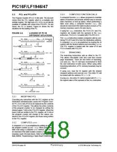
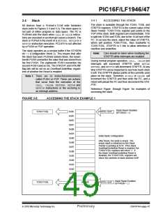
FIGURE 3-5:
ACCESSING THE STACK EXAMPLE 1
Stack Reset Disabled
STKPTR = 0x1F
TOSH:TOSL
0x0F
0x0E
0x0D
0x0C
0x0B
0x0A
0x09
0x08
0x07
0x06
0x05
0x04
0x03
0x02
0x01
0x00
0x1F
(STVREN = 0)
Initial Stack Configuration:
After Reset, the stack is empty. The
empty stack is initialized so the Stack
Pointer is pointing at 0x1F. If the Stack
Overflow/Underflow Reset is enabled, the
TOSH/TOSL registers will return ‘0’. If
the Stack Overflow/Underflow Reset is
disabled, the TOSH/TOSL registers will
return the contents of stack address 0x0F.
Stack Reset Enabled
STKPTR = 0x1F
TOSH:TOSL
0x0000
(STVREN = 1)
2010 Microchip Technology Inc.
Preliminary
DS41414A-page 47

 MICROCHIP [ MICROCHIP ]