PIC16F/LF1946/47
The contrast control circuit is used to decrease the
output voltage of the signal source by a total of
approximately 10%, when LCDCST = 111.
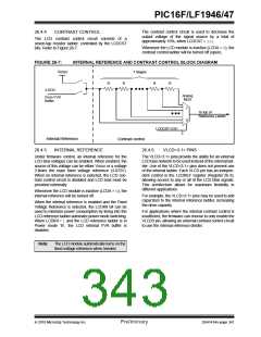
26.4.4
CONTRAST CONTROL
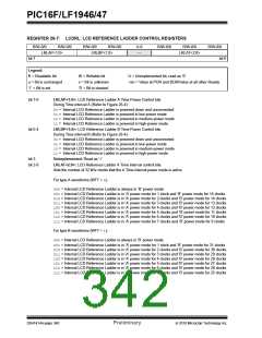
The LCD contrast control circuit consists of a
seven-tap resistor ladder, controlled by the LCDCST
bits. Refer to Figure 26-7.
Whenever the LCD module is inactive (LCDA = 0), the
contrast control ladder will be turned off (open).
FIGURE 26-7:
INTERNAL REFERENCE AND CONTRAST CONTROL BLOCK DIAGRAM
VDDIO
7 Stages
R
R
R
R
3.072V
Analog
MUX
From FVR
Buffer
7
0
To top of
Reference Ladder
LCDCST<2:0>
3
Internal Reference
Contrast control
26.4.5
INTERNAL REFERENCE
26.4.6
VLCD<3:1> PINS
Under firmware control, an internal reference for the
LCD bias voltages can be enabled. When enabled, the
source of this voltage can be either VDDIO or a voltage
3 times the main fixed voltage reference (3.072V).
When no internal reference is selected, the LCD con-
trast control circuit is disabled and LCD bias must be
provided externally.
The VLCD<3:1> pins provide the ability for an external
LCD bias network to be used instead of the internal lad-
der. Use of the VLCD<3:1> pins does not prevent use
of the internal ladder. Each VLCD pin has an indepen-
dent control in the LCDREF register (Register 26-3),
allowing access to any or all of the LCD Bias signals.
This architecture allows for maximum flexibility in
different applications
Whenever the LCD module is inactive (LCDA = 0), the
internal reference will be turned off.
For example, the VLCD<3:1> pins may be used to add
capacitors to the internal reference ladder, increasing
the drive capacity.
When the internal reference is enabled and the Fixed
Voltage Reference is selected, the LCDIRI bit can be
used to minimize power consumption by tieing into the
LCD reference ladder automatic power mode switching.
When LCDIRI = 1 and the LCD reference ladder is in
Power mode ‘B’, the LCD internal FVR buffer is
disables.
For applications where the internal contrast control is
insufficient, the firmware can choose to only enable the
VLCD3 pin, allowing an external contrast control circuit
to use the internal reference divider.
.
Note:
The LCD module automatically turns on the
fixed voltage reference when needed.
2010 Microchip Technology Inc.
Preliminary
DS41414A-page 341

 MICROCHIP [ MICROCHIP ]