PIC16F/LF1946/47
REGISTER 26-7: LCDRL: LCD REFERENCE LADDER CONTROL REGISTERS
R/W-0/0
R/W-0/0
R/W-0/0
R/W-0/0
U-0
—
R/W-0/0
R/W-0/0
R/W-0/0
LRLAP<1:0>
LRLBP<1:0>
LRLAT<2:0>
bit 7
bit 0
Legend:
R = Readable bit
W = Writable bit
U = Unimplemented bit, read as ‘0’
-n/n = Value at POR and BOR/Value at all other Resets
u = Bit is unchanged
‘1’ = Bit is set
x = Bit is unknown
‘0’ = Bit is cleared
bit 7-6
bit 5-4
LRLAP<1:0>: LCD Reference Ladder A Time Power Control bits
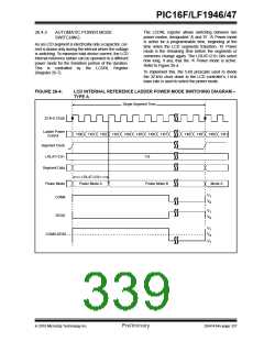
During Time interval A (Refer to Figure 26-4):
00= Internal LCD Reference Ladder is powered down and unconnected
01= Internal LCD Reference Ladder is powered in low-power mode
10= Internal LCD Reference Ladder is powered in medium-power mode
11= Internal LCD Reference Ladder is powered in high-power mode
LRLBP<1:0>: LCD Reference Ladder B Time Power Control bits
During Time interval B (Refer to Figure 26-4):
00= Internal LCD Reference Ladder is powered down and unconnected
01= Internal LCD Reference Ladder is powered in low-power mode
10= Internal LCD Reference Ladder is powered in medium-power mode
11= Internal LCD Reference Ladder is powered in high-power mode
bit 3
Unimplemented: Read as ‘0’
bit 2-0
LRLAT<2:0>: LCD Reference Ladder A Time interval control bits
Sets the number of 32 kHz clocks that the A Time interval power mode is active
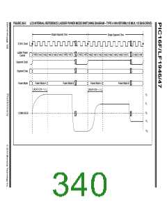
For type A waveforms (WFT = 0):
000= Internal LCD Reference Ladder is always in ‘B’ power mode
001= Internal LCD Reference Ladder is in ‘A’ power mode for 1 clock and ‘B’ power mode for 15 clocks
010= Internal LCD Reference Ladder is in ‘A’ power mode for 2 clocks and ‘B’ power mode for 14 clocks
011= Internal LCD Reference Ladder is in ‘A’ power mode for 3 clocks and ‘B’ power mode for 13 clocks
100= Internal LCD Reference Ladder is in ‘A’ power mode for 4 clocks and ‘B’ power mode for 12 clocks
101= Internal LCD Reference Ladder is in ‘A’ power mode for 5 clocks and ‘B’ power mode for 11 clocks
110= Internal LCD Reference Ladder is in ‘A’ power mode for 6 clocks and ‘B’ power mode for 10 clocks
111= Internal LCD Reference Ladder is in ‘A’ power mode for 7 clocks and ‘B’ power mode for 9 clocks
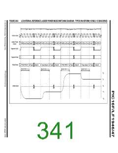
For type B waveforms (WFT = 1):
000= Internal LCD Reference Ladder is always in ‘B’ power mode.
001= Internal LCD Reference Ladder is in ‘A’ power mode for 1 clock and ‘B’ power mode for 31 clocks
010= Internal LCD Reference Ladder is in ‘A’ power mode for 2 clocks and ‘B’ power mode for 30 clocks
011= Internal LCD Reference Ladder is in ‘A’ power mode for 3 clocks and ‘B’ power mode for 29 clocks
100= Internal LCD Reference Ladder is in ‘A’ power mode for 4 clocks and ‘B’ power mode for 28 clocks
101= Internal LCD Reference Ladder is in ‘A’ power mode for 5 clocks and ‘B’ power mode for 27 clocks
110= Internal LCD Reference Ladder is in ‘A’ power mode for 6 clocks and ‘B’ power mode for 26 clocks
111= Internal LCD Reference Ladder is in ‘A’ power mode for 7 clocks and ‘B’ power mode for 25 clocks
DS41414A-page 340
Preliminary
2010 Microchip Technology Inc.

 MICROCHIP [ MICROCHIP ]