PIC16F/LF1946/47
The LCDs can be driven by two types of waveform:
Type-A and Type-B. In Type-A waveform, the phase
changes within each common type, whereas in Type-B
waveform, the phase changes on each frame
boundary. Thus, Type-A waveform maintains 0 VDC
over a single frame, whereas Type-B waveform takes
two frames.
26.9 LCD Waveform Generation
LCD waveforms are generated so that the net AC
voltage across the dark pixel should be maximized and
the net AC voltage across the clear pixel should be
minimized. The net DC voltage across any pixel should
be zero.
The COM signal represents the time slice for each
common, while the SEG contains the pixel data.
Note 1: If Sleep has to be executed with LCD
Sleep disabled (LCDCON<SLPEN> is
‘1’), then care must be taken to execute
Sleep only when VDC on all the pixels is
‘0’.
The pixel signal (COM-SEG) will have no DC
component and it can take only one of the two RMS
values. The higher RMS value will create a dark pixel
and a lower RMS value will create a clear pixel.
2: When the LCD clock source is FOSC/256,
if Sleep is executed, irrespective of the
LCDCON<SLPEN> setting, the LCD
immediately goes into Sleep. Thus, take
care to see that VDC on all pixels is ‘0’
when Sleep is executed.
As the number of commons increases, the delta
between the two RMS values decreases. The delta
represents the maximum contrast that the display can
have.
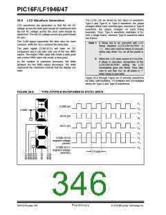
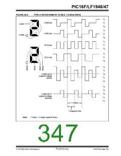
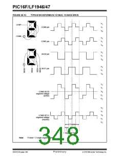
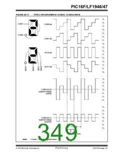
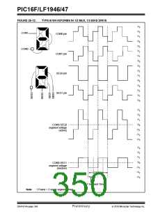
Figure 26-8 through Figure 26-18 provide waveforms
for static, half-multiplex, 1/3-multiplex and 1/4-multiplex
drives for Type-A and Type-B waveforms.
FIGURE 26-8:
TYPE-A/TYPE-B WAVEFORMS IN STATIC DRIVE
V1
COM0 pin
SEG0 pin
SEG1 pin
V0
V1
COM0
V0
V1
V0
V1
V0
COM0-SEG0
segment voltage
(active)
-V1
COM0-SEG1
segment voltage
(inactive)
V0
1 Frame
DS41414A-page 344
Preliminary
2010 Microchip Technology Inc.

 MICROCHIP [ MICROCHIP ]