PIC16F/LF1946/47
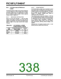
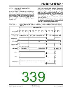
The LCDRL register allows switching between two
power modes, designated ‘A’ and ‘B’. ‘A’ Power mode
is active for a programmable time, beginning at the
time when the LCD segments transition. ‘B’ Power
mode is the remaining time before the segments or
commons change again. The LRLAT<2:0> bits select
how long, if any, that the ‘A’ Power mode is active.
Refer to Figure 26-4.
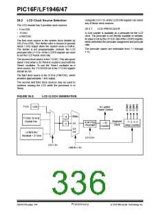
26.4.3
AUTOMATIC POWER MODE
SWITCHING
As an LCD segment is electrically only a capacitor, cur-
rent is drawn only during the interval where the voltage
is switching. To minimize total device current, the LCD
internal reference ladder can be operated in a different
power mode for the transition portion of the duration.
This is controlled by the LCDRL Register
(Register 26-7).
To implement this, the 5-bit prescaler used to divide
the 32 kHz clock down to the LCD controller’s 1 kHz
base rate is used to select the power mode.
FIGURE 26-4:
LCD INTERNAL REFERENCE LADDER POWER MODE SWITCHING DIAGRAM –
TYPE A
Single Segment Time
32 kHz Clock
Ladder Power
Control
‘H00 ‘H01 ‘H02 ‘H03 ‘H04 ‘H05 ‘H06 ‘H07
‘H0E ‘H0F ‘H00 ‘H01
Segment Clock
LRLAT<2:0>
‘H3
Segment Data
LRLAT<2:0>
Power Mode
COM0
Power Mode A
Power Mode B
Mode A
V1
V0
V1
V0
SEG0
V1
V0
COM0-SEG0
-V1
2010 Microchip Technology Inc.
Preliminary
DS41414A-page 337

 MICROCHIP [ MICROCHIP ]