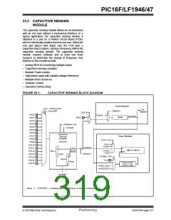
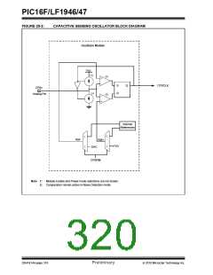
PIC16F/LF1946/47
25.5 Timer Resources
25.7 Software Control
To measure the change in frequency of the capacitive
sensing oscillator, a fixed time base is required. For the
period of the fixed time base, the capacitive sensing
oscillator is used to clock either Timer0 or Timer1. The
frequency of the capacitive sensing oscillator is equal
to the number of counts in the timer divided by the
period of the fixed time base.
The software portion of the capacitive sensing module
is required to determine the change in frequency of the
capacitive sensing oscillator. This is accomplished by
the following:
• Setting a fixed time base to acquire counts on
Timer0 or Timer1.
• Establishing the nominal frequency for the
capacitive sensing oscillator.
25.6 Fixed Time Base
• Establishing the reduced frequency for the capac-
itive sensing oscillator due to an additional capac-
itive load.
To measure the frequency of the capacitive sensing
oscillator, a fixed time base is required. Any timer
resource or software loop can be used to establish the
fixed time base. It is up to the end user to determine the
method in which the fixed time base is generated.
• Set the frequency threshold.
25.7.1
NOMINAL FREQUENCY
(NO CAPACITIVE LOAD)
Note:
The fixed time base can not be generated
by the timer resource that the capacitive
sensing oscillator is clocking.
To determine the nominal frequency of the capacitive
sensing oscillator:
• Remove any extra capacitive load on the selected
CPSx pin.
25.6.1
TIMER0
To select Timer0 as the timer resource for the capacitive
sensing module:
• At the start of the fixed time base, clear the timer
resource.
• At the end of the fixed time base save the value in
the timer resource.
• Set the T0XCS bit of the CPSCON0 register.
• Clear the TMR0CS bit of the OPTION register.
The value of the timer resource is the number of
oscillations of the capacitive sensing oscillator for the
given time base. The frequency of the capacitive
sensing oscillator is equal to the number of counts on
in the timer divided by the period of the fixed time base.
When Timer0 is chosen as the timer resource, the
capacitive sensing oscillator will be the clock source for
Timer0. Refer to Section 19.0 “Timer0 Module” for
additional information.
25.6.2
TIMER1
25.7.2
REDUCED FREQUENCY
To select Timer1 as the timer resource for the
capacitive sensing module, set the TMR1CS<1:0> of
the T1CON register to ‘11’. When Timer1 is chosen as
the timer resource, the capacitive sensing oscillator will
be the clock source for Timer1. Because the Timer1
module has a gate control, developing a time base for
the frequency measurement can be simplified by using
the Timer0 overflow flag.
(ADDITIONAL CAPACITIVE LOAD)
The extra capacitive load will cause the frequency of the
capacitive sensing oscillator to decrease. To determine
the reduced frequency of the capacitive sensing
oscillator:
• Add a typical capacitive load on the selected
CPSx pin.
It is recommend that the Timer0 overflow flag, in
conjunction with the Toggle mode of the Timer1 Gate, be
used to develop the fixed time base required by the soft-
ware portion of the capacitive sensing module. Refer to
Section 20.12 “Timer1 Gate Control Register” for
additional information.
• Use the same fixed time base as the nominal
frequency measurement.
• At the start of the fixed time base, clear the timer
resource.
• At the end of the fixed time base save the value in
the timer resource.
The value of the timer resource is the number of oscil-
lations of the capacitive sensing oscillator with an addi-
tional capacitive load. The frequency of the capacitive
sensing oscillator is equal to the number of counts on
in the timer divided by the period of the fixed time base.
This frequency should be less than the value obtained
during the nominal frequency measurement.
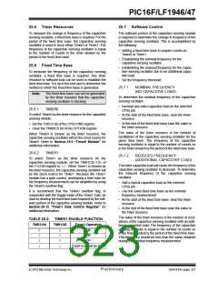
TABLE 25-2: TIMER1 ENABLE FUNCTION
TMR1ON
TMR1GE
Timer1 Operation
0
0
1
0
1
0
Off
Off
On
1
1
Count Enabled by input
2010 Microchip Technology Inc.
Preliminary
DS41414A-page 321

 MICROCHIP [ MICROCHIP ]