PIC16F/LF1946/47
BRGH and SPxBRGL registers are clocked at 1/8th the
BRG base clock rate. The resulting byte measurement
is the average bit time when clocked at full speed.
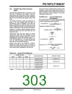
24.3.1
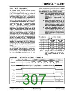
AUTO-BAUD DETECT
The EUSART module supports automatic detection
and calibration of the baud rate.
Note 1: If the WUE bit is set with the ABDEN bit,
auto-baud detection will occur on the byte
following the Break character (see
In the Auto-Baud Detect (ABD) mode, the clock to the
BRG is reversed. Rather than the BRG clocking the
incoming RXx signal, the RXx signal is timing the BRG.
The Baud Rate Generator is used to time the period of
a received 55h (ASCII “U”) which is the Sync character
for the LIN bus. The unique feature of this character is
that it has five rising edges including the Stop bit edge.
Section 24.3.3
“Auto-Wake-up
on
Break”).
2: It is up to the user to determine that the
incoming character baud rate is within the
range of the selected BRG clock source.
Some combinations of oscillator frequency
and EUSART baud rates are not possible.
Setting the ABDEN bit of the BAUDxCON register
starts
the
auto-baud
calibration
sequence
(Figure 24.3.2). While the ABD sequence takes place,
the EUSART state machine is held in Idle. On the first
rising edge of the receive line, after the Start bit, the
SPxBRGL begins counting up using the BRG counter
clock as shown in Table 24-6. The fifth rising edge will
occur on the RXx/DTx pin at the end of the eighth bit
period. At that time, an accumulated value totaling the
proper BRG period is left in the SPxBRGH:SPxBRGL
register pair, the ABDEN bit is automatically cleared,
and the RCxIF interrupt flag is set. A read operation on
the RCxREG needs to be performed to clear the RCxIF
interrupt. RCxREG content should be discarded. When
calibrating for modes that do not use the SPxBRGH
register the user can verify that the SPxBRGL register
did not overflow by checking for 00h in the SPxBRGH
register.
3: During the auto-baud process, the
auto-baud counter starts counting at 1.
Upon completion of the auto-baud
sequence, to achieve maximum accuracy,
subtract 1 from the SPxBRGH:SPxBRGL
register pair.
TABLE 24-6: BRG COUNTER CLOCK
RATES
BRG Base
Clock
BRG ABD
Clock
BRG16 BRGH
0
0
0
1
FOSC/64
FOSC/16
FOSC/512
FOSC/128
The BRG auto-baud clock is determined by the BRG16
and BRGH bits as shown in Table 24-6. During ABD,
both the SPxBRGH and SPxBRGL registers are used
as a 16-bit counter, independent of the BRG16 bit set-
ting. While calibrating the baud rate period, the SPx-
1
1
0
1
FOSC/16
FOSC/4
FOSC/128
FOSC/32
Note:
During the ABD sequence, SPxBRGL and
SPxBRGH registers are both used as a
16-bit counter, independent of BRG16
setting.
FIGURE 24-6:
AUTOMATIC BAUD RATE CALIBRATION
XXXXh
0000h
001Ch
BRG Value
Edge #5
Stop bit
Edge #1
bit 1
Edge #2
bit 3
Edge #3
bit 5
Edge #4
bit 7
bit 6
RXx/DTx pin
BRG Clock
Start
bit 0
bit 2
bit 4
Auto Cleared
Set by User
ABDEN bit
RCIDL
RCxIF bit
(Interrupt)
Read
RCxREG
XXh
XXh
1Ch
00h
SPxBRGL
SPxBRGH
Note 1: The ABD sequence requires the EUSART module to be configured in Asynchronous mode.
2010 Microchip Technology Inc.
Preliminary
DS41414A-page 305

 MICROCHIP [ MICROCHIP ]