PIC16F/LF1946/47
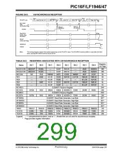
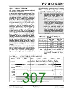
If the system clock is changed during an active receive
operation, a receive error or data loss may result. To
avoid this problem, check the status of the RCIDL bit to
make sure that the receive operation is Idle before
changing the system clock.
24.3 EUSART Baud Rate Generator
(BRG)
The Baud Rate Generator (BRG) is an 8-bit or 16-bit
timer that is dedicated to the support of both the
asynchronous and synchronous EUSART operation.
By default, the BRG operates in 8-bit mode. Setting the
BRG16 bit of the BAUDxCON register selects 16-bit
mode.
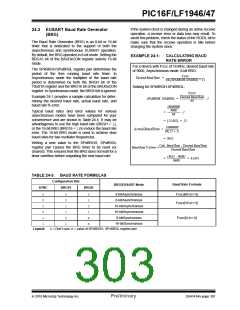
EXAMPLE 24-1:
CALCULATING BAUD
RATE ERROR
For a device with FOSC of 16 MHz, desired baud rate
of 9600, Asynchronous mode, 8-bit BRG:
The SPxBRGH:SPxBRGL register pair determines the
period of the free running baud rate timer. In
Asynchronous mode the multiplier of the baud rate
period is determined by both the BRGH bit of the
TXxSTA register and the BRG16 bit of the BAUDxCON
register. In Synchronous mode, the BRGH bit is ignored.
FOSC
Desired Baud Rate = -------------------------------------------------------------------------
64[SPxBRGH:SPxBRG] + 1
Solving for SPxBRGH:SPxBRGL:
FOSC
---------------------------------------------
Example 24-1 provides a sample calculation for deter-
mining the desired baud rate, actual baud rate, and
baud rate % error.
Desired Baud Rate
SPxBRGH: SPxBRGL = --------------------------------------------- – 1
64
16000000
-----------------------
9600
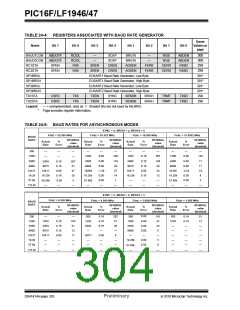
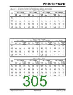
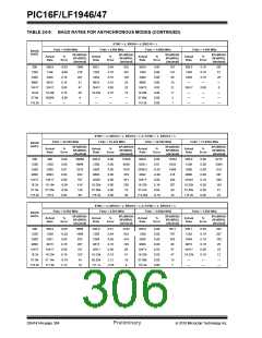
Typical baud rates and error values for various
asynchronous modes have been computed for your
convenience and are shown in Table 24-5. It may be
advantageous to use the high baud rate (BRGH = 1),
or the 16-bit BRG (BRG16 = 1) to reduce the baud rate
error. The 16-bit BRG mode is used to achieve slow
baud rates for fast oscillator frequencies.
= ----------------------- – 1
64
= 25.042 = 25
16000000
ActualBaudRate = --------------------------
6425 + 1
= 9615
Writing a new value to the SPxBRGH, SPxBRGL
register pair causes the BRG timer to be reset (or
cleared). This ensures that the BRG does not wait for a
timer overflow before outputting the new baud rate.
Calc. Baud Rate – Desired Baud Rate
Baud Rate % Error =--------------------------------------------------------------------------------------------
Desired Baud Rate
9615 – 9600
= ---------------------------------- = 0 . 1 6 %
9600
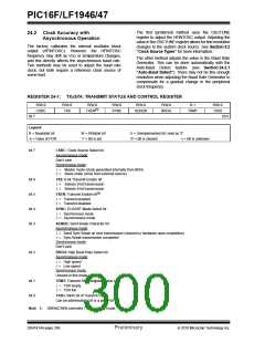
TABLE 24-3: BAUD RATE FORMULAS
Configuration Bits
Baud Rate Formula
BRG/EUSART Mode
SYNC
BRG16
BRGH
0
0
0
0
1
1
0
0
1
1
0
1
0
1
0
1
x
x
8-bit/Asynchronous
8-bit/Asynchronous
16-bit/Asynchronous
16-bit/Asynchronous
8-bit/Synchronous
16-bit/Synchronous
FOSC/[64 (n+1)]
FOSC/[16 (n+1)]
FOSC/[4 (n+1)]
Legend:
x= Don’t care, n = value of SPxBRGH, SPxBRGL register pair
2010 Microchip Technology Inc.
Preliminary
DS41414A-page 301

 MICROCHIP [ MICROCHIP ]