PIC16F/LF1946/47
I2C MASTER MODE RECEPTION
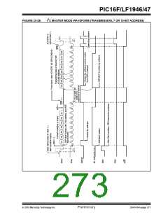
23.6.7.4 Typical Receive Sequence:
23.6.7
Master mode reception is enabled by programming the
Receive Enable bit, RCEN bit of the SSPxCON2
register.
1. The user generates a Start condition by setting
the SEN bit of the SSPxCON2 register.
2. SSPxIF is set by hardware on completion of the
Start.
Note:
The MSSPx module must be in an Idle
state before the RCEN bit is set or the
RCEN bit will be disregarded.
3. SSPxIF is cleared by software.
4. User writes SSPxBUF with the slave address to
transmit and the R/W bit set.
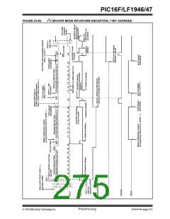
The Baud Rate Generator begins counting and on each
rollover, the state of the SCLx pin changes
(high-to-low/low-to-high) and data is shifted into the
SSPxSR. After the falling edge of the eighth clock, the
receive enable flag is automatically cleared, the con-
tents of the SSPxSR are loaded into the SSPxBUF, the
BF flag bit is set, the SSPxIF flag bit is set and the Baud
Rate Generator is suspended from counting, holding
SCLx low. The MSSPx is now in Idle state awaiting the
next command. When the buffer is read by the CPU,
the BF flag bit is automatically cleared. The user can
then send an Acknowledge bit at the end of reception
by setting the Acknowledge Sequence Enable, ACKEN
bit of the SSPxCON2 register.
5. Address is shifted out the SDAx pin until all 8 bits
are transmitted. Transmission begins as soon
as SSPxBUF is written to.
6. The MSSPx module shifts in the ACK bit from
the slave device and writes its value into the
ACKSTAT bit of the SSPxCON2 register.
7. The MSSPx module generates an interrupt at
the end of the ninth clock cycle by setting the
SSPxIF bit.
8. User sets the RCEN bit of the SSPxCON2 regis-
ter and the Master clocks in a byte from the slave.
9. After the 8th falling edge of SCLx, SSPxIF and
BF are set.
10. Master clears SSPxIF and reads the received
byte from SSPxUF, clears BF.
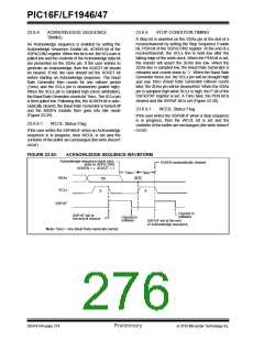
23.6.7.1
BF Status Flag
In receive operation, the BF bit is set when an address
or data byte is loaded into SSPxBUF from SSPxSR. It
is cleared when the SSPxBUF register is read.
11. Master sets ACK value sent to slave in ACKDT
bit of the SSPxCON2 register and initiates the
ACK by setting the ACKEN bit.
23.6.7.2
SSPxOV Status Flag
12. Masters ACK is clocked out to the Slave and
SSPxIF is set.
In receive operation, the SSPxOV bit is set when 8 bits
are received into the SSPxSR and the BF flag bit is
already set from a previous reception.
13. User clears SSPxIF.
14. Steps 8-13 are repeated for each received byte
from the slave.
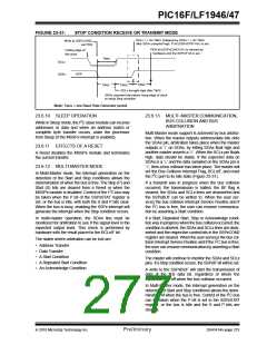
23.6.7.3
WCOL Status Flag
15. Master sends a not ACK or Stop to end
communication.
If the user writes the SSPxBUF when a receive is
already in progress (i.e., SSPxSR is still shifting in a
data byte), the WCOL bit is set and the contents of the
buffer are unchanged (the write doesn’t occur).
DS41414A-page 272
Preliminary
2010 Microchip Technology Inc.

 MICROCHIP [ MICROCHIP ]