PIC16F/LF1946/47
I2C MASTER/
23.3 I2C MODE OVERVIEW
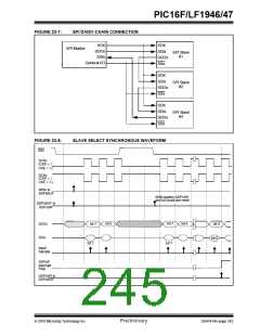
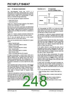
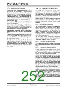
FIGURE 23-11:
SLAVE CONNECTION
The Inter-Integrated Circuit Bus (I²C™) is
a
multi-master serial data communication bus. Devices
communicate in a master/slave environment where the
master devices initiate the communication. A Slave
device is controlled through addressing.
VDD
SCLx
SCLx
The I2C bus specifies two signal connections:
VDD
• Serial Clock (SCLx)
• Serial Data (SDAx)
Master
Slave
SDAx
SDAx
Figure 23-11 shows the block diagram of the MSSPx
module when operating in I2C Mode.
Both the SCLx and SDAx connections are bidirectional
open-drain lines, each requiring pull-up resistors for the
supply voltage. Pulling the line to ground is considered
a logical zero and letting the line float is considered a
logical one.
The Acknowledge bit (ACK) is an active-low signal,
which holds the SDAx line low to indicate to the trans-
mitter that the slave device has received the transmit-
ted data and is ready to receive more.
Figure 23-11 shows a typical connection between two
processors configured as master and slave devices.
The I2C bus can operate with one or more master
devices and one or more slave devices.
The transition of a data bit is always performed while
the SCLx line is held low. Transitions that occur while
the SCLx line is held high are used to indicate Start and
Stop bits.
If the master intends to write to the slave, then it repeat-
edly sends out a byte of data, with the slave responding
after each byte with an ACK bit. In this example, the
master device is in Master Transmit mode and the
slave is in Slave Receive mode.
There are four potential modes of operation for a given
device:
• Master Transmit mode
(master is transmitting data to a slave)
• Master Receive mode
If the master intends to read from the slave, then it
repeatedly receives a byte of data from the slave, and
responds after each byte with an ACK bit. In this exam-
ple, the master device is in Master Receive mode and
the slave is Slave Transmit mode.
(master is receiving data from a slave)
• Slave Transmit mode
(slave is transmitting data to a master)
• Slave Receive mode
(slave is receiving data from the master)
On the last byte of data communicated, the master
device may end the transmission by sending a Stop bit.
If the master device is in Receive mode, it sends the
Stop bit in place of the last ACK bit. A Stop bit is indi-
cated by a low-to-high transition of the SDAx line while
the SCLx line is held high.
To begin communication, a master device starts out in
Master Transmit mode. The master device sends out a
Start bit followed by the address byte of the slave it
intends to communicate with. This is followed by a sin-
gle Read/Write bit, which determines whether the mas-
ter intends to transmit to or receive data from the slave
device.
In some cases, the master may want to maintain con-
trol of the bus and re-initiate another transmission. If
so, the master device may send another Start bit in
place of the Stop bit or last ACK bit when it is in receive
mode.
If the requested slave exists on the bus, it will respond
with an Acknowledge bit, otherwise known as an ACK.
The master then continues in either Transmit mode or
Receive mode and the slave continues in the comple-
ment, either in Receive mode or Transmit mode,
respectively.
The I2C bus specifies three message protocols;
• Single message where a master writes data to a
slave.
A Start bit is indicated by a high-to-low transition of the
SDAx line while the SCLx line is held high. Address and
data bytes are sent out, Most Significant bit (MSb) first.
The Read/Write bit is sent out as a logical one when the
master intends to read data from the slave, and is sent
out as a logical zero when it intends to write data to the
slave.
• Single message where a master reads data from
a slave.
• Combined message where a master initiates a
minimum of two writes, or two reads, or a
combination of writes and reads, to one or more
slaves.
DS41414A-page 246
Preliminary
2010 Microchip Technology Inc.

 MICROCHIP [ MICROCHIP ]