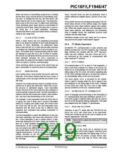
PIC16F/LF1946/47
When one device is transmitting a logical one, or letting
the line float, and a second device is transmitting a log-
ical zero, or holding the line low, the first device can
detect that the line is not a logical one. This detection,
when used on the SCLx line, is called clock stretching.
Clock stretching gives slave devices a mechanism to
control the flow of data. When this detection is used on
the SDAx line, it is called arbitration. Arbitration
ensures that there is only one master device communi-
cating at any single time.
Slave Transmit mode can also be arbitrated, when a
master addresses multiple slaves, but this is less com-
mon.
If two master devices are sending a message to two dif-
ferent slave devices at the address stage, the master
sending the lower slave address always wins arbitra-
tion. When two master devices send messages to the
same slave address, and addresses can sometimes
refer to multiple slaves, the arbitration process must
continue into the data stage.
Arbitration usually occurs very rarely, but it is a neces-
sary process for proper multi-master support.
23.3.1
CLOCK STRETCHING
When a slave device has not completed processing
data, it can delay the transfer of more data through the
process of Clock Stretching. An addressed slave
device may hold the SCLx clock line low after receiving
or sending a bit, indicating that it is not yet ready to con-
tinue. The master that is communicating with the slave
will attempt to raise the SCLx line in order to transfer
the next bit, but will detect that the clock line has not yet
been released. Because the SCLx connection is
open-drain, the slave has the ability to hold that line low
until it is ready to continue communicating.
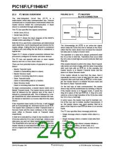
23.4 I2C Mode Operation
All MSSPx I2C communication is byte oriented and
shifted out MSb first. Six SFR registers and 2 interrupt
flags interface the module with the PIC® microcon-
troller and user software. Two pins, SDAx and SCLx,
are exercised by the module to communicate with
other external I2C devices.
23.4.1 BYTE FORMAT
All communication in I2C is done in 9-bit segments. A
byte is sent from a Master to a Slave or vice-versa, fol-
lowed by an Acknowledge bit sent back. After the 8th
falling edge of the SCLx line, the device outputting data
on the SDAx changes that pin to an input and reads in
an acknowledge value on the next clock pulse.
Clock stretching allows receivers that cannot keep up
with a transmitter to control the flow of incoming data.
23.3.2
ARBITRATION
Each master device must monitor the bus for Start and
Stop bits. If the device detects that the bus is busy, it
cannot begin a new message until the bus returns to an
Idle state.
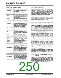
The clock signal, SCLx, is provided by the master.
Data is valid to change while the SCLx signal is low,
and sampled on the rising edge of the clock. Changes
on the SDAx line while the SCLx line is high define
special conditions on the bus, explained below.
However, two master devices may try to initiate a trans-
mission on or about the same time. When this occurs,
the process of arbitration begins. Each transmitter
checks the level of the SDAx data line and compares it
to the level that it expects to find. The first transmitter to
observe that the two levels don’t match, loses arbitra-
tion, and must stop transmitting on the SDAx line.
23.4.2 DEFINITION OF I2C TERMINOLOGY
There is language and terminology in the description of
I2C communication that have definitions specific to I2C.
That word usage is defined below and may be used in
the rest of this document without explanation. This table
was adapted from the Phillips I2C specification.
For example, if one transmitter holds the SDAx line to
a logical one (lets it float) and a second transmitter
holds it to a logical zero (pulls it low), the result is that
the SDAx line will be low. The first transmitter then
observes that the level of the line is different than
expected and concludes that another transmitter is
communicating.
23.4.3 SDAX AND SCLX PINS
Selection of any I2C mode with the SSPxEN bit set,
forces the SCLx and SDAx pins to be open-drain.
These pins should be set by the user to inputs by set-
ting the appropriate TRIS bits.
The first transmitter to notice this difference is the one
that loses arbitration and must stop driving the SDAx
line. If this transmitter is also a master device, it also
must stop driving the SCLx line. It then can monitor the
lines for a Stop condition before trying to reissue its
transmission. In the meantime, the other device that
has not noticed any difference between the expected
and actual levels on the SDAx line continues with its
original transmission. It can do so without any compli-
cations, because so far, the transmission appears
exactly as expected with no other transmitter disturbing
the message.
Note: Data is tied to output zero when an I2C mode
is enabled.
23.4.4 SDAX HOLD TIME
The hold time of the SDAx pin is selected by the
SDAHT bit of the SSPxCON3 register. Hold time is the
time SDAx is held valid after the falling edge of SCLx.
Setting the SDAHT bit selects a longer 300 ns mini-
mum hold time and may help on buses with large
capacitance.
2010 Microchip Technology Inc.
Preliminary
DS41414A-page 247

 MICROCHIP [ MICROCHIP ]