PIC16F/LF1946/47
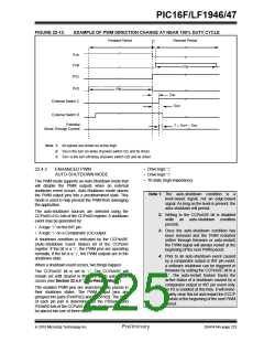
drivers are enabled. Changing the polarity
configuration while the PWM pin output drivers are
enable is not recommended since it may result in
damage to the application circuits.
22.4.6.1
Steering Synchronization
The STRxSYNC bit of the PSTRxCON register gives
the user two selections of when the steering event will
happen. When the STRxSYNC bit is ‘0’, the steering
event will happen at the end of the instruction that
writes to the PSTRxCON register. In this case, the
output signal at the Px<D:A> pins may be an
incomplete PWM waveform. This operation is useful
when the user firmware needs to immediately remove
a PWM signal from the pin.
The PxA, PxB, PxC and PxD output latches may not be
in the proper states when the PWM module is
initialized. Enabling the PWM pin output drivers at the
same time as the Enhanced PWM modes may cause
damage to the application circuit. The Enhanced PWM
modes must be enabled in the proper Output mode and
complete a full PWM cycle before enabling the PWM
pin output drivers. The completion of a full PWM cycle
is indicated by the TMRxIF bit of the PIRx register
being set as the second PWM period begins.
When the STRxSYNC bit is ‘1’, the effective steering
update will happen at the beginning of the next PWM
period. In this case, steering on/off the PWM output will
always produce a complete PWM waveform.
Note:
When the microcontroller is released from
Reset, all of the I/O pins are in the
high-impedance state. The external cir-
cuits must keep the power switch devices
in the Off state until the microcontroller
drives the I/O pins with the proper signal
levels or activates the PWM output(s).
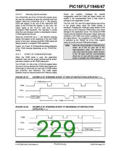
Figures 22-19 and 22-20 illustrate the timing diagrams
of the PWM steering depending on the STRxSYNC
setting.
22.4.7
START-UP CONSIDERATIONS
When any PWM mode is used, the application
hardware must use the proper external pull-up and/or
pull-down resistors on the PWM output pins.
The CCPxM<1:0> bits of the CCPxCON register allow
the user to choose whether the PWM output signals are
active-high or active-low for each pair of PWM output
pins (PxA/PxC and PxB/PxD). The PWM output
polarities must be selected before the PWM pin output
FIGURE 22-19:
EXAMPLE OF STEERING EVENT AT END OF INSTRUCTION (STRxSYNC = 0)
PWM Period
PWM
STRx
P1<D:A>
PORT Data
PORT Data
P1n = PWM
FIGURE 22-20:
EXAMPLE OF STEERING EVENT AT BEGINNING OF INSTRUCTION
(STRxSYNC = 1)
PWM
STRx
P1<D:A>
PORT Data
PORT Data
P1n = PWM
2010 Microchip Technology Inc.
Preliminary
DS41414A-page 227

 MICROCHIP [ MICROCHIP ]