PIC16F/LF1946/47
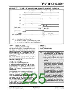
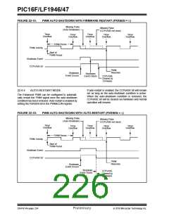
FIGURE 22-13:
EXAMPLE OF PWM DIRECTION CHANGE AT NEAR 100% DUTY CYCLE
Forward Period
Reverse Period
t1
PxA
PxB
PW
PxC
PxD
PW
TON
External Switch C
External Switch D
TOFF
Potential
T = TOFF – TON
Shoot-Through Current
Note 1: All signals are shown as active-high.
2: TON is the turn on delay of power switch QC and its driver.
3: TOFF is the turn off delay of power switch QD and its driver.
• Drive logic ‘1’
• Drive logic ‘0’
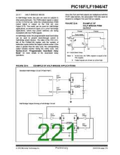
22.4.3
ENHANCED PWM
AUTO-SHUTDOWN MODE
• Tri-state (high-impedance)
The PWM mode supports an Auto-Shutdown mode that
will disable the PWM outputs when an external
shutdown event occurs. Auto-Shutdown mode places
the PWM output pins into a predetermined state. This
mode is used to help prevent the PWM from damaging
the application.
Note 1: The auto-shutdown condition is
a
level-based signal, not an edge-based
signal. As long as the level is present, the
auto-shutdown will persist.
The auto-shutdown sources are selected using the
CCPxAS<2:0> bits of the CCPxAS register. A shutdown
event may be generated by:
2: Writing to the CCPxASE bit is disabled
while an auto-shutdown condition
persists.
• A logic ‘0’ on the INT pin
3: Once the auto-shutdown condition has
been removed and the PWM restarted
(either through firmware or auto-restart)
the PWM signal will always restart at the
beginning of the next PWM period.
• A logic ‘1’ on a Comparator (Cx) output
A shutdown condition is indicated by the CCPxASE
(Auto-Shutdown Event Status) bit of the CCPxAS
register. If the bit is a ‘0’, the PWM pins are operating
normally. If the bit is a ‘1’, the PWM outputs are in the
shutdown state.
4: Prior to an auto-shutdown event caused
by a comparator output or INT pin event,
a software shutdown can be triggered in
firmware by setting the CCPxASE bit to a
‘1’. The auto-restart feature tracks the
active status of a shutdown caused by a
comparator output or INT pin event only,
so if it is enabled at this time, it will imme-
diately clear this bit and restart the ECCP
module at the beginning of the next PWM
period.
When a shutdown event occurs, two things happen:
The CCPxASE bit is set to ‘1’. The CCPxASE will
remain set until cleared in firmware or an auto-restart
occurs (see Section 22.4.4 “Auto-Restart Mode”).
The enabled PWM pins are asynchronously placed in
their shutdown states. The PWM output pins are
grouped into pairs [PxA/PxC] and [PxB/PxD]. The state
of each pin pair is determined by the PSSxAC and
PSSxBD bits of the CCPxAS register. Each pin pair may
be placed into one of three states:
2010 Microchip Technology Inc.
Preliminary
DS41414A-page 223

 MICROCHIP [ MICROCHIP ]