PIC16F/LF1946/47
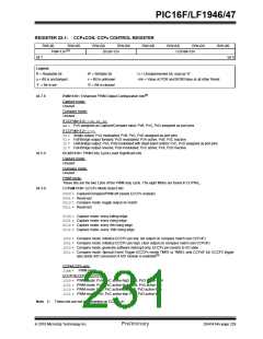
REGISTER 22-1: CCPxCON: CCPx CONTROL REGISTER
R/W-00
PxM<1:0>
R/W-0/0
(1)
R/W-0/0
R/W-0/0
R/W-0/0
R/W-0/0
R/W-0/0
R/W-0/0
DCxB<1:0>
CCPxM<3:0>
bit 7
bit 0
Legend:
R = Readable bit
W = Writable bit
x = Bit is unknown
‘0’ = Bit is cleared
U = Unimplemented bit, read as ‘0’
u = Bit is unchanged
‘1’ = Bit is set
-n/n = Value at POR and BOR/Value at all other Reset
(1)
bit 7-6
PxM<1:0>: Enhanced PWM Output Configuration bits
Capture mode:
Unused
Compare mode:
Unused
If CCPxM<3:2> = 00, 01, 10:
xx= PxA assigned as Capture/Compare input; PxB, PxC, PxD assigned as port pins
If CCPxM<3:2> = 11:
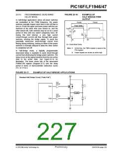
00= Single output; PxA modulated; PxB, PxC, PxD assigned as port pins
01= Full-Bridge output forward; PxD modulated; PxA active; PxB, PxC inactive
10= Half-Bridge output; PxA, PxB modulated with dead-band control; PxC, PxD assigned as port pins
11= Full-Bridge output reverse; PxB modulated; PxC active; PxA, PxD inactive
bit 5-4
DCxB<1:0>: PWM Duty Cycle Least Significant bits
Capture mode:
Unused
Compare mode:
Unused
PWM mode:
These bits are the two LSbs of the PWM duty cycle. The eight MSbs are found in CCPRxL.
bit 3-0
CCPxM<3:0>: ECCPx Mode Select bits
0000= Capture/Compare/PWM off (resets ECCPx module)
0001= Reserved
0010= Compare mode: toggle output on match
0011= Reserved
0100= Capture mode: every falling edge
0101= Capture mode: every rising edge
0110= Capture mode: every 4th rising edge
0111= Capture mode: every 16th rising edge
1000= Compare mode: initialize ECCPx pin low; set output on compare match (set CCPxIF)
1001= Compare mode: initialize ECCPx pin high; clear output on compare match (set CCPxIF)
1010= Compare mode: generate software interrupt only; ECCPx pin reverts to I/O state
1011= Compare mode: Special Event Trigger (ECCPx resets TMR1 or TMR3, sets CCPxIF bit, ECCP2 trigger
(1)
also starts A/D conversion if A/D module is enabled)
CCP4/CCP5 only:
11xx= PWM mode
ECCP1/ECCP2/ECCP3 only:
1100= PWM mode: PxA, PxC active-high; PxB, PxD active-high
1101= PWM mode: PxA, PxC active-high; PxB, PxD active-low
1110= PWM mode: PxA, PxC active-low; PxB, PxD active-high
1111= PWM mode: PxA, PxC active-low; PxB, PxD active-low
Note 1: These bits are not implemented on CCP<5:4>.
2010 Microchip Technology Inc.
Preliminary
DS41414A-page 229

 MICROCHIP [ MICROCHIP ]