PIC16F/LF1946/47
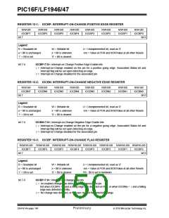
REGISTER 13-1: IOCBP: INTERRUPT-ON-CHANGE POSITIVE EDGE REGISTER
R/W-0/0
IOCBP7
R/W-0/0
IOCBP6
R/W-0/0
IOCBP5
R/W-0/0
IOCBP4
R/W-0/0
IOCBP3
R/W-0/0
IOCBP2
R/W-0/0
IOCBP1
R/W-0/0
IOCBP0
bit 7
bit 0
Legend:
R = Readable bit
W = Writable bit
U = Unimplemented bit, read as ‘0’
-n/n = Value at POR and BOR/Value at all other Resets
u = Bit is unchanged
‘1’ = Bit is set
x = Bit is unknown
‘0’ = Bit is cleared
bit 7-0
IOCBP<7:0>: Interrupt-on-Change Positive Edge Enable bits
1= Interrupt-on-Change enabled on the pin for a positive going edge. Associated Status bit and
interrupt flag will be set upon detecting an edge.
0= Interrupt-on-Change disabled for the associated pin.
REGISTER 13-2: IOCBN: INTERRUPT-ON-CHANGE NEGATIVE EDGE REGISTER
R/W-0/0
IOCBN7
R/W-0/0
IOCBN6
R/W-0/0
IOCBN5
R/W-0/0
IOCBN4
R/W-0/0
IOCBN3
R/W-0/0
IOCBN2
R/W-0/0
IOCBN1
R/W-0/0
IOCBN0
bit 7
bit 0
Legend:
R = Readable bit
W = Writable bit
U = Unimplemented bit, read as ‘0’
-n/n = Value at POR and BOR/Value at all other Resets
u = Bit is unchanged
‘1’ = Bit is set
x = Bit is unknown
‘0’ = Bit is cleared
bit 7-0
IOCBN<7:0>: Interrupt-on-Change Negative Edge Enable bits
1= Interrupt-on-Change enabled on the pin for a negative going edge. Associated Status bit and
interrupt flag will be set upon detecting an edge.
0= Interrupt-on-Change disabled for the associated pin.
REGISTER 13-3: IOCBF: INTERRUPT-ON-CHANGE FLAG REGISTER
R/W/HS-0/0 R/W/HS-0/0 R/W/HS-0/0 R/W/HS-0/0 R/W/HS-0/0 R/W/HS-0/0 R/W/HS-0/0 R/W/HS-0/0
IOCBF7
bit 7
IOCBF6
IOCBF5
IOCBF4
IOCBF3
IOCBF2
IOCBF1
IOCBF0
bit 0
Legend:
R = Readable bit
W = Writable bit
U = Unimplemented bit, read as ‘0’
u = Bit is unchanged
‘1’ = Bit is set
x = Bit is unknown
‘0’ = Bit is cleared
-n/n = Value at POR and BOR/Value at all other Resets
HS - Bit is set in hardware
bit 7-0
IOCBF<7:0>: Interrupt-on-Change Flag bits
1= An enabled change was detected on the associated pin.
Set when IOCBPx = 1and a rising edge was detected on RBx, or when IOCBNx = 1and a falling
edge was detected on RBx.
0= No change was detected, or the user cleared the detected change.
DS41414A-page 148
Preliminary
2010 Microchip Technology Inc.

 MICROCHIP [ MICROCHIP ]