PIC16F/LF1946/47
13.3 Interrupt Flags
13.0 INTERRUPT-ON-CHANGE
The IOCBFx bits located in the IOCBF register are
status flags that correspond to the Interrupt-on-change
pins of PORTB. If an expected edge is detected on an
appropriately enabled pin, then the status flag for that pin
will be set, and an interrupt will be generated if the IOCIE
bit is set. The IOCIF bit of the INTCON register reflects
the status of all IOCBFx bits.
The PORTB pins can be configured to operate as
Interrupt-On-Change (IOC) pins. An interrupt can be
generated by detecting a signal that has either a rising
edge or a falling edge. Any individual PORTB pin, or
combination of PORTB pins, can be configured to
generate an interrupt. The interrupt-on-change module
has the following features:
• Interrupt-on-Change enable (Master Switch)
• Individual pin configuration
13.4 Clearing Interrupt Flags
• Rising and falling edge detection
• Individual pin interrupt flags
The individual status flags, (IOCBFx bits), can be
cleared by resetting them to zero. If another edge is
detected during this clearing operation, the associated
status flag will be set at the end of the sequence,
regardless of the value actually being written.
Figure 13-1 is a block diagram of the IOC module.
13.1 Enabling the Module
In order to ensure that no detected edge is lost while
clearing flags, only AND operations masking out known
changed bits should be performed. The following
sequence is an example of what should be performed.
To allow individual PORTB pins to generate an interrupt,
the IOCIE bit of the INTCON register must be set. If the
IOCIE bit is disabled, the edge detection on the pin will
still occur, but an interrupt will not be generated.
EXAMPLE 13-1:
13.2 Individual Pin Configuration
MOVLW 0xff
XORWF IOCBF, W
ANDWF IOCBF, F
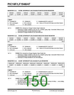
For each PORTB pin, a rising edge detector and a falling
edge detector are present. To enable a pin to detect a
rising edge, the associated IOCBPx bit of the IOCBP
register is set. To enable a pin to detect a falling edge,
the associated IOCBNx bit of the IOCBN register is set.
13.5 Operation in Sleep
The interrupt-on-change interrupt sequence will wake
the device from Sleep mode, if the IOCIE bit is set.
A pin can be configured to detect rising and falling
edges simultaneously by setting both the IOCBPx bit
and the IOCBNx bit of the IOCBP and IOCBN registers,
respectively.
If an edge is detected while in Sleep mode, the IOCBF
register will be updated prior to the first instruction
executed out of Sleep.
FIGURE 13-1:
INTERRUPT-ON-CHANGE BLOCK DIAGRAM
IOCIE
IOCBFx
IOCBNx
D
Q
From all other IOCBFx
individual pin detectors
CK
R
IOC Interrupt to
CPU Core
RBx
IOCBPx
D
Q
CK
R
Q2 Clock Cycle
2010 Microchip Technology Inc.
Preliminary
DS41414A-page 147

 MICROCHIP [ MICROCHIP ]