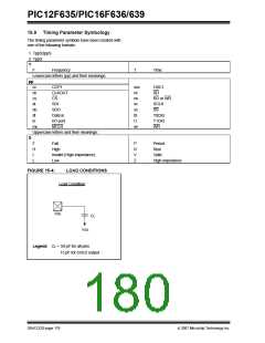
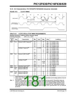
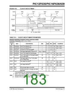
PIC12F635/PIC16F636/639
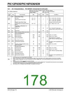
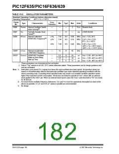
15.8 Thermal Considerations
Standard Operating Conditions (unless otherwise stated)
Operating temperature
-40°C ≤ TA ≤ +125°C
Para
m
Sym
Characteristic
Typ
Units
Conditions
No.
TH01 θJA
Thermal Resistance
Junction to Ambient
84.6 °C/W 8-pin PDIP package
163.0 °C/W 8-pin SOIC package
PIC12F635
PIC16F636
52.4 °C/W 8-pin DFN 4x4x0.9 mm package
52.4 °C/W 8-pin DFN-S 6x5 mm package
69.8 °C/W 14-pin PDIP package
85.0 °C/W 14-pin SOIC package
100.4 °C/W 14-pin TSSOP package
46.3 °C/W 16-pin QFN 4x0.9mm package
PIC16F639 108.1 °C/W 20-pin SSOP package
41.2 °C/W 8-pin PDIP package
TH02 θJC
Thermal Resistance
Junction to Case
38.8 °C/W 8-pin SOIC package
PIC12F635
3.0
3.0
°C/W 8-pin DFN 4x4x0.9 mm package
°C/W 8-pin DFN-S 6x5 mm package
32.5 °C/W 14-pin PDIP package
31.0 °C/W 14-pin SOIC package
31.7 °C/W 14-pin TSSOP package
PIC16F636
2.6
°C/W 16-pin QFN 4x0.9mm package
PIC16F639 32.2 °C/W 20-pin SSOP package
TH03 TJ
TH04 PD
Junction Temperature
Power Dissipation
150
—
°C For derated power calculations
W
W
PD = PINTERNAL + PI/O
TH05 PINTERNAL Internal Power Dissipation
—
PINTERNAL = IDD x VDD
(NOTE 1)
TH06 PI/O
I/O Power Dissipation
Derated Power
—
—
W
W
PI/O = Σ (IOL * VOL) + Σ (IOH * (VDD - VOH))
PDER = (TJ - TA)/θJA
(NOTE 2, 3)
TH07 PDER
Note 1: IDD is current to run the chip alone without driving any load on the output pins.
2: TA = Ambient Temperature.
3: Maximum allowable power dissipation is the lower value of either the absolute maximum total power
dissipation or derated power (PDER).
© 2007 Microchip Technology Inc.
DS41232D-page 177

 MICROCHIP [ MICROCHIP ]