MCP414X/416X/424X/426X
4.2.1
NON-VOLATILE MEMORY
(EEPROM)
4.2.1.4
Special Features
There are 3 non-volatile bits that are not directly
mapped into the address space. These bits control the
following functions:
This memory can be grouped into two uses of
non-volatile memory. These are:
• EEPROM Write Protect
• General Purpose Registers
• Non-Volatile Wiper Registers
• WiperLock Technology for Non-Volatile Wiper 0
• WiperLock Technology for Non-Volatile Wiper 1
The non-volatile wipers starts functioning below the
devices VPOR/VBOR trip point.
The operation of WiperLock Technology is discussed in
Section 5.3. The state of the WL0, WL1, and WP bits
is reflected in the STATUS register (see Register 4-1).
4.2.1.1
General Purpose Registers
These locations allow the user to store up to 10 (9-bit)
locations worth of information.
EEPROM Write Protect
All internal EEPROM memory can be Write Protected.
When EEPROM memory is Write Protected, Write
commands to the internal EEPROM are prevented.
4.2.1.2
Non-Volatile Wiper Registers
These locations contain the wiper values that are
loaded into the corresponding volatile wiper register
whenever the device has a POR/BOR event. There are
up to two registers, one for each resistor network.
Write Protect (WP) can be enabled/disabled by two
methods. These are:
• External WP Hardware pin (MCP42X1 devices
only)
The non-volatile wiper register enables stand-alone
operation of the device (without Microcontroller control)
after being programmed to the desired value.
• Non-Volatile configuration bit
High Voltage commands are required to enable and
disable the nonvolatile WP bit. These commands are
shown in Section 7.9 “Modify Write Protect or Wip-
erLock Technology (High Voltage)”.
4.2.1.3
Factory Initialization of Non-Volatile
Memory (EEPROM)
The Non-Volatile Wiper values will be initialized to
mid-scale value. This is shown in Table 4-2.
To write to EEPROM, both the external WP pin and the
internal WP EEPROM bit must be disabled. Write
Protect does not block commands to the volatile
registers.
The General purpose EEPROM memory will be
programmed to a default value of 0xFF.
It is good practice in the manufacturing flow to
configure the device to your desired settings.
4.2.2
VOLATILE MEMORY (RAM)
There are four Volatile Memory locations. These are:
• Volatile Wiper 0
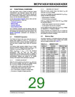
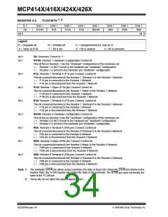
TABLE 4-2:
DEFAULT FACTORY
SETTINGS SELECTION
• Volatile Wiper 1
(Dual Resistor Network devices only)
Wiper
Code
• Status Register
• Terminal Control (TCON) Register
The volatile memory starts functioning at the RAM
retention voltage (VRAM).
8-bit 7-bit
-502
5.0 kΩ Mid-scale 80h 40h Disabled
-103 10.0 kΩ Mid-scale 80h 40h Disabled
-503 50.0 kΩ Mid-scale 80h 40h Disabled
-104 100.0 kΩ Mid-scale 80h 40h Disabled
DS22059B-page 30
© 2008 Microchip Technology Inc.

 MICROCHIP [ MICROCHIP ]