MCP2515
Therefore:
PROPAGATION SEGMENT
The Propagation Segment (PropSeg) exists to
compensate for physical delays between nodes. The
propagation delay is defined as twice the sum of the
signal’s propagation time on the bus line, including the
delays associated with the bus driver. The PropSeg is
programmable from 1 – 8 TQ.
PS2
= IPT = 2TQ
min
SYNCHRONIZATION JUMP WIDTH
The Synchronization Jump Width (SJW) adjusts the bit
clock as necessary by 1 – 4 TQ (as configured) to
maintain synchronization with the transmitted
message. Synchronization is covered in more detail
later in this data sheet.
PHASE SEGMENT 1 (PS1) AND PHASE
SEGMENT 2 (PS2)
The two phase segments, PS1 and PS2, are used to
compensate for edge phase errors on the bus. PS1 can
be lengthened (or PS2 shortened) by resyncronization.
PS1 is programmable from 1 – 8 TQ and PS2 is
programmable from 2 – 8 TQ.
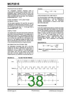
Time Quantum
Each of the segments that make up a bit time are made
up of integer units called Time Quanta (TQ). The length
of each Time Quantum is based on the oscillator period
(tOSC). The base TQ equals twice the oscillator period.
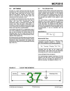
Figure 5-2 shows how the bit period is derived from
TOSC and TQ. The TQ length equals one TQ clock
period (tBRPCLK), which is programmable using a
programmable prescaler, called the Baud Rate
Prescaler (BRP). This is illustrated in the following
equation:
SAMPLE POINT
The sample point is the point in the bit time at which the
logic level is read and interpreted. The sample point is
located at the end of PS1. The exception to this rule is
if the sample mode is configured to sample three times
per bit. In this case, while the bit is still sampled at the
end of PS1, two additional samples are taken at one-
half TQ intervals prior to the end of PS1, with the value
of the bit being determined by a majority decision.
EQUATION 5-2:
INFORMATION PROCESSING TIME
2 ⋅ BRP
TQ = 2 ⋅ BRP ⋅ T
= ------------------
OSC
The Information Processing Time (IPT) is the time
required for the logic to determine the bit level of a
sampled bit. The IPT begins at the sample point, is
measured in TQ and is fixed at 2 TQ for the Microchip
CAN module. Since PS2 also begins at the sample
point and is the last segment in the bit time, it is
required that the PS2 minimum is not less than the IPT.
F
OSC
Where: BRP equals the configuration as shown in
Register 5-1.
FIGURE 5-2:
TQ AND THE BIT PERIOD
tOSC
TBRPCLK
Sync
(fixed)
PropSeg
(Programmable)
PS1
(Programmable)
PS2
(Programmable)
tBIT
TQ
(tTQ)
CAN Bit Time
DS21801D-page 38
Preliminary
© 2005 Microchip Technology Inc.

 MICROCHIP [ MICROCHIP ]