MCP2515
5.1
The CAN Bit TIme
5.0
BIT TIMING
All devices on the CAN bus must use the same bit rate.
However, all devices are not required to have the same
master oscillator clock frequency. For the different
clock frequencies of the individual devices, the bit rate
has to be adjusted by appropriately setting the baud
rate prescaler and number of time quanta in each
segment.
All nodes on a given CAN bus must have the same
nominal bit rate. The CAN protocol uses Non Return to
Zero (NRZ) coding, which does not encode a clock
within the data stream. Therefore, the receive clock
must be recovered by the receiving nodes and
synchronized to the transmitter’s clock.
As oscillators and transmission times may vary from
node to node, the receiver must have some type of
Phase Lock Loop (PLL) synchronized to data
transmission edges to synchronize and maintain the
receiver clock. Since the data is NRZ-coded, it is
necessary to include bit-stuffing to insure that an edge
occurs at least every six bit times to maintain the Digital
Phase Lock Loop (DPLL) synchronization.
The CAN bit time is made up of non-overlapping
segments. Each of these segments are made up of
integer units called Time Quanta (TQ), explained later
in this data sheet. The Nominal Bit Rate (NBR) is
defined in the CAN specification as the number of bits
per second transmitted by an ideal transmitter with no
resynchronization. It can be described with the
equation:
The bit timing of the MCP2515 is implemented using a
DPLL that is configured to synchronize to the incoming
data, as well as provide the nominal timing for the
transmitted data. The DPLL breaks each bit time into
multiple segments made up of minimal periods of time,
called the Time Quanta (TQ).
EQUATION 5-1:
1
tbit
NBR = f
= ------
bit
Bus timing functions executed within the bit time frame
(such as synchronization to the local oscillator, network
transmission delay compensation and sample point
positioning) are defined by the programmable bit timing
logic of the DPLL.
Nominal Bit Time
The Nominal Bit Time (NBT) (tbit) is made up of non-
overlapping segments (Figure 5-1). Therefore, the
NBT is the summation of the following segments:
t
= t
+ t
+ t
+ t
bit
SyncSeg
PropSeg PS1 PS2
Associated with the NBT are the sample point,
Synchronization Jump Width (SJW) and Information
Processing Time (IPT), which are explained later.
SYNCHRONIZATION SEGMENT
The Synchronization Segment (SyncSeg) is the first
segment in the NBT and is used to synchronize the
nodes on the bus. Bit edges are expected to occur
within the SyncSeg. This segment is fixed at 1 TQ.
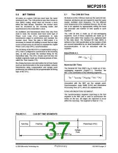
FIGURE 5-1:
CAN BIT TIME SEGMENTS
SyncSeg
PropSeg
PhaseSeg1 (PS1)
PhaseSeg2 (PS2)
Sample
Point
Nominal Bit Time (NBT), tbit
© 2005 Microchip Technology Inc.
Preliminary
DS21801D-page 37

 MICROCHIP [ MICROCHIP ]