MCP2200
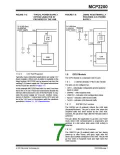
FIGURE 1-4:
TYPICAL POWER SUPPLY
OPTION USING THE 5V
PROVIDED BY THE USB
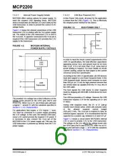
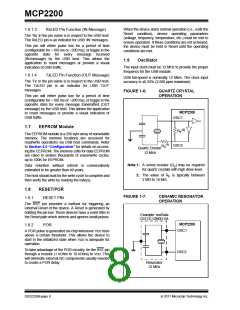
FIGURE 1-5:
USING AN EXTERNALLY
PROVIDED 3.3V POWER
SUPPLY
5V (USB Bus)
or external
power supply
5V (USB Bus)
or external
power supply
External
3.3V
LDO
VDD
VDD
IN
LDO
IN
LDO
3.3V
3.3V
OUT
VUSB
VUSB
OUT
D+
D-
D+
D-
USB
Transceiver
USB
Transceiver
1.5.2.3
3.3V Self Powered
1.6
GPIO Module
Typically, many embedded applications are using 3.3V
power supplies. When such an option is available in the
target system, MCP2200 can be powered up from the
existing 3.3V power supply rail. The typical connections
for MCP2200 are shown in Figure 1-5.
The GPIO Module is a standard 8-bit I/O port.
1.6.1 CONFIGURABLE PIN FUNCTIONS
The pins can be configured as:
• GPIO – individually configurable general purpose
input or output
In this example MCP2200 has both VDD and VUSB lines
tied to the 3.3V rail. These tied connections disable the
internal USB transceiver LDO of the MCP2200 to reg-
ulate the power supply on VUSB pin. Another conse-
quence is that the ‘1’ logical level on the GPIO pins will
be at the 3.3V level, in accordance with the variations
specified in Section 3.1, DC Characteristics.
• SSPND – USB Suspend state
• USBCFG – indicates USB configuration status
• RxLED – indicates USB receive traffic
• TxLED – indicates USB transmit traffic
1.6.1.1
SSPND Pin Function
The SSPND pin (if enabled) reflects the USB state
(Suspend/Resume). The pin is active ‘low’ when the
Suspend state has been issued by the USB host.
Likewise, the pin drives ‘high’ after the Resume state is
achieved.
This pin allows the application to go into Low Power
mode when USB communication is suspended, and
switches to a full active state when USB activity is
resumed.
1.6.1.2
USBCFG Pin Function
The USBCFG pin (if enabled) starts out ‘low’ during
power-up or after Reset, and goes ‘high’ after the
device successfully configures to the USB. The pin will
go ‘low’ when in Suspend mode and ‘high’ when the
USB resumes.
2011 Microchip Technology Inc.
DS22228B-page 7

 MICROCHIP [ MICROCHIP ]