MCP2200
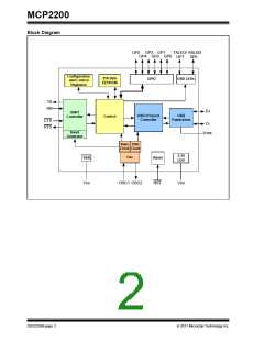
The MCP2200 has eight general purpose input/output
pins. Four pins have alternate functions to indicate
USB and communication status. See Table 1-1 and
Section 1.6 “GPIO Module” for details about the pin
functions.
1.0
FUNCTIONAL DESCRIPTION
The MCP2200 is a USB-to-UART serial converter
which enables USB connectivity in applications that
have a UART interface. The device reduces external
components by integrating the USB termination
resistors. The MCP2200 also has 256 bytes of
integrated user EEPROM.
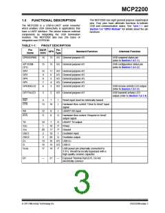
TABLE 1-1:
PINOUT DESCRIPTION
Pin
Name
SSOP,
SOIC
Pin
Type
QFN
Standard Function
Alternate Function
GP0/SSPND
16
13
I/O General purpose I/O
I/O General purpose I/O
USB suspend status pin
(refer to Section 1.6.1.1)
GP1/USB-
CFG
15
12
USB configuration status pin
(refer to Section 1.6.1.2)
GP2
14
9
11
6
I/O General purpose I/O
I/O General purpose I/O
I/O General purpose I/O
I/O General purpose I/O
I/O General purpose I/O
GP3
GP4
8
5
GP5
7
4
GP6/RxLED
6
3
USB receive activity LED output
(refer to Section 1.6.1.3)
GP7/TxLED
5
2
I/O General purpose I/O
USB transmit activity LED
output (refer to Section 1.6.1.4)
RST
CTS
4
1
I
I
Reset input must be externally biased
13
10
Hardware flow control “Clear to Send” input
signal
RX
12
11
9
8
I
USART RX input
RTS
O
Hardware flow control “Request to Send”
output signal
TX
10
1
7
O
P
P
I
USART TX output
Power
VDD
VSS
OSC1
OSC2
D+
18
17
19
20
16
15
14
20
2
Ground
Oscillator input
Oscillator output
3
O
19
18
17
I/O USB D+
I/O USB D-
D-
VUSB
P
USB power pin (internally connected to
3.3V). Should be locally bypassed with a
high quality ceramic capacitor.
EP
—
21
—
Exposed Thermal Pad (EP). Do not
electrically connect.
2011 Microchip Technology Inc.
DS22228B-page 3

 MICROCHIP [ MICROCHIP ]