MCP2200
1.3.1
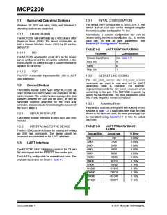
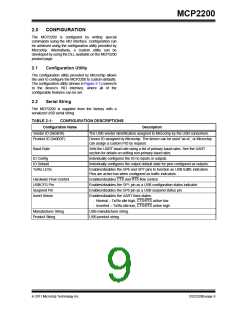
INITIAL CONFIGURATION
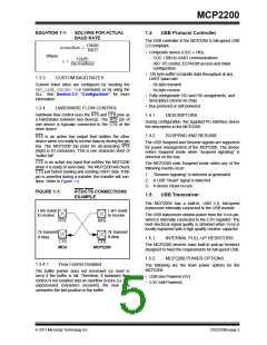
1.1
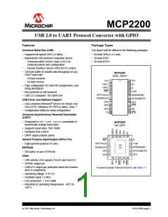
Supported Operating Systems
The default UART configuration is 19200, 8, N, 1. The
default start up baud rate can be changed using the
Microchip-supplied configuration PC tool.
Windows XP (SP2 and later), Vista, and Windows 7
operating systems are supported.
1.1.1
ENUMERATION
Alternatively, a custom configuration tool can be
created using the Microchip-supplied DLL to set the
baud rate, as well as other parameters. See
Section 2.0 “Configuration” for details.
The MCP2200 will enumerate as a USB device after
Power-on Reset (POR). The device enumerates as
both a Human Interface Device (HID) for I/O control,
and a VCP.
TABLE 1-2:
UART CONFIGURATIONS
Configuration
See Table 1-3
1.1.1.1
HID
Parameter
The MCP2200 enumerates as an HID, so the device
can be configured and the I/O can be controlled. A DLL
that facilitates I/O control through a custom interface is
supplied by Microchip.
Primary Baud Rates
Data Bits
8
N
1
Parity
Stop Bits
1.1.1.2
VCP
The VCP enumeration implements the USB-to-UART
data translation.
1.3.2
GET/SET LINE CODING
The GET_LINE_CODING and SET_LINE_CODING
commands are used to read and set the UART
parameters while in operation. For example,
Hyperterminal sends the SET_LINE_COMMAND when
connecting to the port. The MCP2200 responds by
setting the baud rate only. The other parameters (Data
Bits, Parity, Stop Bits) remain unchanged.
1.2
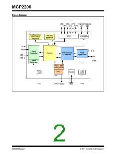
Control Module
The control module is the heart of the MCP2200. All
other modules are tied together and controlled via the
control module. The control module manages the data
transfers between the USB and the UART, as well as
command requests generated by the USB host
controller, and commands for controlling the function of
the UART and I/O.
1.3.2.1
Rounding Errors
The primary baud rate setting (with the rounding errors)
is shown in Table 1-3. If baud rates other than the ones
shown in the table are used, the error percentage can
be calculated using Equation 1-1 to find the actual
baud rate.
1.2.1
SERIAL INTERFACE
The control module interfaces to the UART and USB
modules.
TABLE 1-3:
UART PRIMARY BAUD
RATES
1.2.2
INTERFACING TO THE DEVICE
The MCP2200 can be accessed for reading and writing
via USB host commands. The device cannot be
accessed and controlled via the UART interface.
Desired Rate
Actual rate
% Error
300
300
1200
0.00%
0.00%
0.00%
0.00%
0.00%
0.00%
0.16%
0.16%
0.16%
0.16%
0.16%
0.16%
1200
1.3
UART Interface
2400
2400
The MCP2200 UART interface consists of the TX and
RX data signals and the RTS/CTS flow control pins.
4800
4800
9600
9600
The UART is configurable for several baud rates. The
available baud rates are listed in Table 1-3.
19200
38400
57600
115200
230400
460800
921600
19200
38339
57692
115385
230769
461538
923077
DS22228B-page 4
2011 Microchip Technology Inc.

 MICROCHIP [ MICROCHIP ]