MCP2200
EQUATION 1-1:
SOLVING FOR ACTUAL
BAUD RATE
1.4
USB Protocol Controller
The USB controller in the MCP2200 is full-speed USB
2.0 compliant.
12MHz
intx
ActualRate = ------------------
• Composite device (CDC + HID):
Where:
- CDC: USB-to-UART communications
12MHz
x = ----------------------------------
DesiredBaud
- HID: I/O control, EEPROM access and initial
configuration
• 128 byte buffer to handle data throughput at any
UART baud rate:
1.3.3
CUSTOM BAUD RATES
- 64-byte transmit
- 64-byte receive
Custom baud rates are configured by sending the
SET_LINE_CODING USB command, or by using the
DLL. See Section 2.0 “Configuration” for more
information.
• Fully configurable VID and PID assignments, and
descriptors (stored on-chip)
• Bus powered or self-powered
1.3.4
HARDWARE FLOW CONTROL
Hardware flow control uses the RTS and CTS pins as
a handshake between two devices. The RTS pin of
one device is typically connected to the CTS of the
other device.
1.4.1
DESCRIPTORS
During configuration, the supplied PC interface stores
the descriptors in the MCP2200.
1.4.2
SUSPEND AND RESUME
RTS is an active low output that notifies the other
device when it is ready to receive data by driving the pin
low. The MCP2200 trip point for de-asserting RTS
(high) is 63 characters. This is one character short of
“buffer full”.
The USB Suspend and Resume signals are supported
for power management of the MCP2200. The device
enters Suspend mode when “suspend signaling” is
detected on the bus.
CTS is an active low input that notifies the MCP2200
when it is ready to send data. The MCP2200 will check
CTS just before loading and sending UART data. If the
pin is asserted during a transfer, the transfer will con-
tinue. Refer to Figure 1.4.
The MCP2200 exits Suspend mode when any of the
following events occur:
1. “Resume signaling” is detected or generated
2. A USB “Reset” signal is detected
3. A device Reset occurs
FIGURE 1-1:
RTS/CTS CONNECTIONS
EXAMPLE
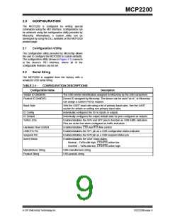
1.5
USB Transceiver
The MCP2200 has a built-in, USB 2.0, full-speed
transceiver internally connected to the USB module.
I am ready
to receive
I am ready
to receive
The USB transceiver obtains power from the VUSB pin,
which is internally connected to the 3.3V regulator. The
best electrical signal quality is obtained when VUSB is
locally bypassed with a high quality ceramic capacitor.
RTS
RTS
I’ll transmit
if okay
I’ll transmit
if okay
1.5.1
INTERNAL PULL-UP RESISTORS
CTS
CTS
The MCP2200 devices have built-in pull-up resistors
designed to meet the requirements for full-speed USB.
MCU
MCP2200
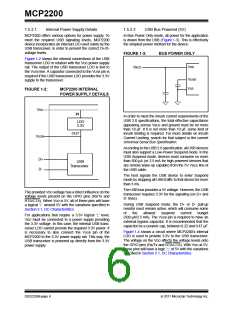
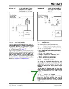
1.5.2
MCP2200 POWER OPTIONS
1.3.4.1
Flow Control Disabled
The following are the main power options for the
MCP2200:
The buffer pointer does not increment (or reset to
zero) if the buffer is full. Therefore, if hardware flow
control is not enabled and an overflow occurs (i.e., 65
unprocessed characters received), the new data
overwrites the last position in the buffer.
• USB Bus Powered (5V)
• 3.3V Self Powered
2011 Microchip Technology Inc.
DS22228B-page 5

 MICROCHIP [ MICROCHIP ]