MCP2021/2
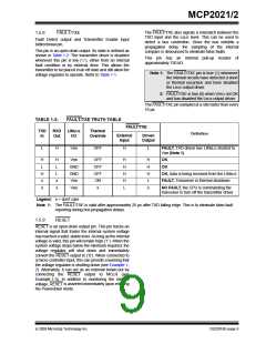
TABLE 1-1:
State
OVERVIEW OF OPERATIONAL MODES
Voltage
Transmitter Receiver
Regulator
Operation
Comments
POR
OFF
OFF
ON
OFF
OFF
Read CS/LWAKE, if LOW, then READY,
if HIGH, Operational mode
READY
Activity
Detect
ON
If CS/LWAKE high level, then Operation Bus Off state
mode
OPERATION
ON
ON
If CS/LWAKE low level, then Power down Normal
If FAULT/TXE low level, then Transmitter- Operation
Off mode
mode
POWER DOWN
OFF
OFF
Activity
Detect
OFF
ON
On LIN bus falling, go to READY mode. Low Power
On CS/LWAKE high level, go to
Operational mode
mode
TRANSMITTER-
OFF
ON
If CS/LWAKE low level, then Power down
If FAULT/TXE high, then Operation mode
1.4
Typical Applications
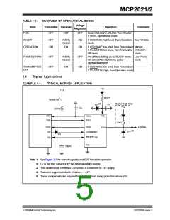
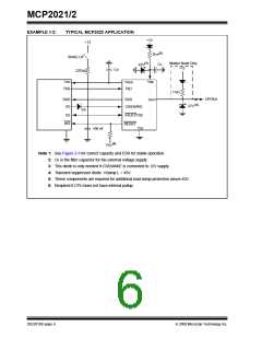
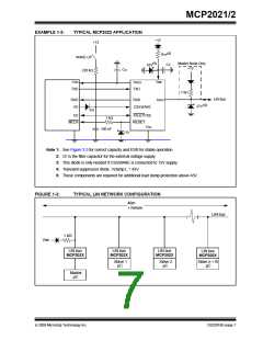
EXAMPLE 1-1:
TYPICAL MCP2021 APPLICATION
+12
+12
(5)
RTP
WAKE-UP
(5)
Master Node Only
+12
CF
43V
CG
220 kΩ
VBB
VDD
VREG
TXD
TXD
1 kΩ
LIN Bus
RXD
I/O
RXD
LBUS
(4)
27V
CS/LWAKE
FAULT/TXE
(3)
I/O
VSS
100nF
Note 1: See Figure 2-3 for correct capacity and ESR for stable operation..
2: CF is the filter capacitor for the external voltage supply.
3: This diode is only needed if CS/LWAKE is connected to 12V supply.
4: Transient suppressor diode. Vclamp L = 43V.
5: These components are required for additional load dump protection above 43V..
© 2009 Microchip Technology Inc.
DS22018E-page 5

 MICROCHIP [ MICROCHIP ]