HCS200
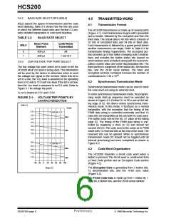
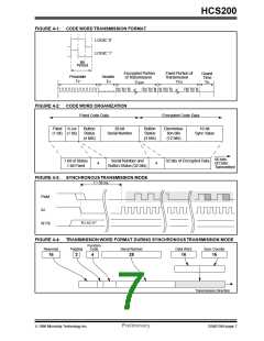
FIGURE 4-1: CODE WORD TRANSMISSION FORMAT
LOGIC ‘0’
LOGIC ‘1’
Bit
Period
Encrypted Portion
Fixed Portion of
Transmission
TFIX
Guard
Time
TG
Header
TH
Preamble
TP
of Transmission
THOP
FIGURE 4-2: CODE WORD ORGANIZATION
Fixed Code Data
Encrypted Code Data
Discrimina-
Fixed VLOW
(1 bit) (1 bit)
Button
Status
(4 bits)
28-bit
Button
Status
(4 bits)
16-bit
Serial Number
tion bits
(12 bits)
Sync Value
66 bits
1 bit of Status
1 bit Fixed
Serial Number and
Button Status (32 bits)
32 bits of Encrypted Data
of Data
+
+
Transmitted
FIGURE 4-3: SYNCHRONOUS TRANSMISSION MODE
t = 50 ms
PWM
S2
“01,10,11”
S[1:0]
FIGURE 4-4: TRANSMISSION WORD FORMAT DURING SYNCHRONOUS TRANSMISSION MODE
Function
Code
Reserved
Padding
Serial Number
Data Word
Sync Counter
16
2
4
28
16
16
Transmission Direction
1996 Microchip Technology Inc.
Preliminary
DS40138A-page 7

 MICROCHIP [ MICROCHIP ]