HCS200
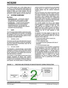
The high security level of the HCS200 is based on the pat-
ented KEELOQ technology. A block cipher based on a block
length of 32 bits and a key length of 64 bits is used. The algo-
rithm obscures the information in such a way that even if the
transmission information (before coding) differs by only one bit
from the information in the previous transmission, the next
coded transmission will be totally different. Statistically, if only
one bit in the 32-bit string of information changes, approxi-
mately 50 percent of the coded transmission will change. The
HCS200 will wake up upon detecting a switch closure and
then delay approximately 10 ms for switch debounce
(Figure 2-2). The synchronization information, fixed informa-
tion, and switch information will be encrypted to form the hop-
ping code. The encrypted or hopping code portion of the
transmission will change every time, even if the same button
is pushed again. A code that has been transmitted will not
occur again for more than 64K transmissions.This will provide
more than 18 years of typical use before a code is repeated
based on 10 operations per day. Overflow information sent
from the encoder can be used by the decoder to extend the
number of unique transmissions to more than 192K.
2.0
DEVICE OPERATION
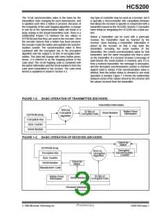
As shown in Figure 2-1, the HCS200 is a simple device
to use. It requires only the addition of buttons and RF
circuitry for use as the transmitter in your security appli-
cation. A description of each pin is described in
Table 2-1.
Note:
When VDD > 9.0V and driving low capacitive
loads, a resistor with a minimum value of 50Ω
should be used in line with VDD. This prevents
clamping of PWM at 9.0V in the event of PWM
overshoot.
FIGURE 2-1: TYPICAL CIRCUITS
+12V
(Note 2) R
B0
B1
S0
VDD
NC
S1
S2
NC
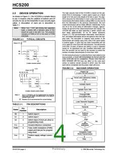
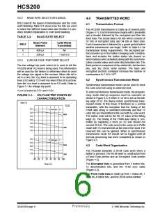
If in the transmit process it is detected that a new button(s) has
been pressed, a reset will immediately be forced and the
code word will not be completed. Please note that but-
tons removed will not have any effect on the code word
unless no buttons remain pressed in which case the code
word will be completed and the power down will occur.
Tx out
PWM
Vss
2 button remote control
FIGURE 2-2: ENCODER OPERATION
+12V
(Note 2) R
Power Up
B3 B2 B1 B0
(A button has been pressed)
Reset and Debounce Delay
S0
VDD
NC
(10 ms)
S1
S2
NC
Tx out
PWM
Vss
Sample Inputs
Update Sync Info
4 button remote control (Note)
Encrypt With
Encryption Key
Note 1:
Up to 7 functions can be implemented by pressing
more than one button simultaneously or by using a
suitable diode array.
2: Resistor (R) is recommended for current limiting.
Load Transmit Register
Transmit
TABLE 2-1:
PIN DESCRIPTIONS
Description
Pin
Name
Number
Buttons
Added
Yes
S0
S1
S2
1
2
3
Switch input 0
Switch input 1
?
No
Switch input 2/Clock pin when in
programming mode
No
All
Buttons
Released
?
VSS
5
6
Ground reference connection
PWM
Pulse width modulation (PWM)
output pin/Data pin for program-
ming mode
Yes
Complete Code
Word Transmission
VDD
8
Positive supply voltage connec-
tion
Stop
DS40138A-page 4
Preliminary
1996 Microchip Technology Inc.

 MICROCHIP [ MICROCHIP ]