HCS200
3.6.2
BAUD RATE SELECT BITS (BSL0)
4.0
TRANSMITTED WORD
BSL0 selects the speed of transmission and the code
word blanking. Table 3-3 shows how the bits are used
to select the different baud rates and Section 5.2 pro-
vides detailed explanation in code word blanking.
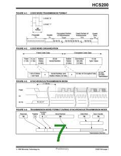
4.1
Transmission Format
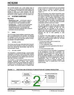
The HCS200 transmission is made up of several parts
(Figure 4-1). Each transmission begins with a preamble
and a header, followed by the encrypted and then the
fixed data. The actual data is 66 bits which consists of
32 bits of encrypted data and 34 bits of fixed data.
Each transmission is followed by a guard period before
another transmission can begin. Refer to Table 8-4 for
transmission timing requirements. The encrypted por-
tion provides up to four billion changing code combina-
tions and includes the button status bits (based on
which buttons were activated) along with the synchroni-
zation counter value and some discrimination bits. The
fixed portion is comprised of the status bits, the function
bits, and the 28-bit serial number. The fixed and
encrypted sections combined increase the number of
TABLE 3-3:
BSL0
BAUD RATE SELECT
Basic Pulse
Code Words
Element
Transmitted
0
1
400 µs
200 µs
All
1 out of 2
3.6.3
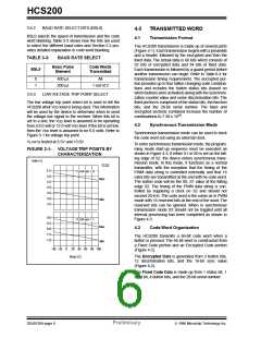
LOW VOLTAGE TRIP POINT SELECT
The low voltage trip point select bit is used to tell the
HCS200 what VDD level is being used.This information
will be used by the device to determine when to send
the voltage low signal to the receiver. When this bit is
set to a one, the VDD level is assumed to be operating
from a 9.0 volt or 12.0 volt VDD level. If the bit is set low,
then the VDD level is assumed to be 6.0 volts. Refer to
Figure 3-1 for voltage trip point.
19
combinations to 7.38 x 10 .
4.2
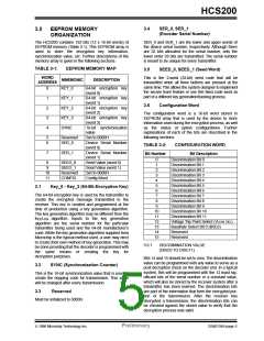
Synchronous Transmission Mode
Synchronous transmission mode can be used to clock
the code word out using an external clock.
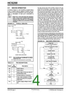
VLOW is tested at 3.5V and 13.0V.
To enter synchronous transmission mode, the program-
ming mode start-up sequence must be executed as
shown in Figure 4-3. If either S1 or S0 is set on the fall-
ing edge of S2, the device enters synchronous trans-
mission mode. In this mode, it functions as a normal
transmitter, with the exception that the timing of the
PWM data string is controlled externally and that 16
extra bits are transmitted at the end with he code word.
The button code will be the S0, S1 value at the falling
edge S2. The timing of the PWM data string is con-
trolled by supplying a clock on S2 and should not
exceed 20 kHz. The code word is the same as in PWM
mode with 16 reserved bits at the end of the word. The
reserved bits can be ignored. When in synchronous
transmission mode S2 should not be toggled until all
internal processing has been completed as shown in
Figure 4-3.
FIGURE 3-1: VOLTAGE TRIP POINTS BY
CHARACTERIZATION
Volts (V)
VLOW
5.5
5.0
4.5
4.0
3.5
3.0
2.5
VLOW sel = 0
Max
Min
9.0
8.5
8.0
7.5
7.0
VLOW sel = 1
Max
Min
4.3
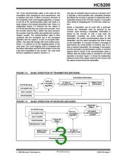
Code Word Organization
The HCS200 transmits a 66-bit code word when a
button is pressed. The 66-bit word is constructed from
a Fixed Code portion and an Encrypted Code portion
(Figure 4-2).
-40 -20
0
20 40 60 80 100
Temp (C)
The Encrypted Data is generated from 3 button bits,
12 discrimination bits, and the 16-bit sync value
(Figure 4-2).
The Fixed Code Data is made up from 1 status bit, 1
fixed bit, 4 button bits, and the 28-bit serial number.
DS40138A-page 6
Preliminary
1996 Microchip Technology Inc.

 MICROCHIP [ MICROCHIP ]