HCS200
3.4
SER_0, SER_1
(Encoder Serial Number)
3.0
EEPROM MEMORY
ORGANIZATION
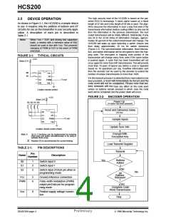
The HCS200 contains 192 bits (12 x 16-bit words) of
EEPROM memory (Table 3-1). This EEPROM array is
used to store the encryption key information,
synchronization value, etc. Further descriptions of the
memory array is given in the following sections.
SER_0 and SER_1 are the lower and upper words of
the device serial number, respectively. Although there
are 32 bits allocated for the serial number, only the
lower order 28 bits are transmitted. The serial number
is meant to be unique for every transmitter.
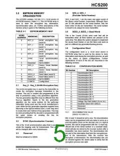
TABLE 3-1:
EEPROM MEMORY MAP
3.5
SEED_0, SEED_1 (Seed Word)
WORD
ADDRESS
This is the 2-word (32-bit) seed code that will be
transmitted when all three buttons are pressed at the
same time.This allows the system designer to implement
the secure learn feature or use this fixed code word as
part of a different key generation/tracking process.
MNEMONIC
DESCRIPTION
0
1
2
3
4
KEY_0
64-bit encryption key
(word 0)
64-bit encryption key
(word 1)
64-bit encryption key
(word 2)
64-bit encryption key
(word 3)
16-bit synchronization
value
Set to 0000H
Device Serial Number
(word 0)
KEY_1
KEY_2
KEY_3
SYNC
3.6
Configuration Word
The configuration word is a 16-bit word stored in
EEPROM array that is used by the device to store
information used during the encryption process, as well
as the status of option configurations. Further
explanations of each of the bits are described in the
following sections.
5
6
Reserved
SER_0
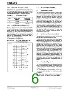
TABLE 3-2:
CONFIGURATION WORD
7
SER_1
Device Serial Number
(word 1)
Seed Value (word 0)
Seed Value (word 1)
Set to 0000H
Bit Number
Bit Description
0
1
2
3
4
5
6
7
8
Discrimination Bit 0
Discrimination Bit 1
Discrimination Bit 2
Discrimination Bit 3
Discrimination Bit 4
Discrimination Bit 5
Discrimination Bit 6
Discrimination Bit 7
Discrimination Bit 8
Discrimination Bit 9
Discrimination Bit 10
Discrimination Bit 11
Voltage Trip Point Select (VLOW SEL)
Baudrate Select Bit 0 (BSL0)
Reserved
8
9
10
11
SEED_0
SEED_1
Reserved
CONFIG
Config Word
3.1
Key_0 - Key_3 (64-Bit Encryption Key)
The 64-bit encryption key is used by the transmitter to
create the encrypted message transmitted to the
receiver. This key is created and programmed at the
time of production using a key generation algorithm.
The key generation algorithm may be different from the
KEELOQ algorithm. Inputs to the key generation
algorithm are the serial number for the particular
transmitter being used and the 64-bit manufacturer’s
code. While the key generation algorithm supplied from
Microchip is the typical method used, a user may elect
to create their own method of key generation. This may
be done providing that the decoder is programmed with
the same means of creating the key for
decryption purposes.
9
10
11
12
13
14
15
Reserved
3.6.1
DISCRIMINATION VALUE
(DISC0 TO DISC11)
Bits 14 and 15 should be set to zero.The discrimination
value can be programmed with any value to serve as a
post decryption check on the decoder end. In a typical
system, this will be programmed with the 12 least sig-
nificant bits of the serial number or a constant value,
which will also be stored by the receiver system after a
transmitter has been learned. The discrimination bits
are part of the information that form the encrypted por-
tion of the transmission. After the receiver has
decrypted a transmission, the discrimination bits can
be checked against the stored value to verify that the
decryption process was valid.
3.2
SYNC (Synchronization Counter)
This is the 16-bit synchronization value that is used to
create the hopping code for transmission. This value
will be changed after every transmission.
3.3
Reserved
Must be initialized to 0000H.
1996 Microchip Technology Inc.
Preliminary
DS40138A-page 5

 MICROCHIP [ MICROCHIP ]