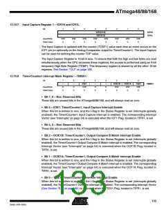
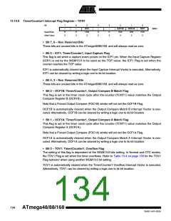
13.10.9 Timer/Counter1 Interrupt Flag Register – TIFR1
Bit
7
–
6
–
5
4
–
3
–
2
OCF1B
R/W
0
1
OCF1A
R/W
0
0
TOV1
R/W
0
ICF1
R/W
0
TIFR1
Read/Write
Initial Value
R
0
R
0
R
0
R
0
• Bit 7, 6 – Res: Reserved Bits
These bits are unused bits in the ATmega48/88/168, and will always read as zero.
• Bit 5 – ICF1: Timer/Counter1, Input Capture Flag
This flag is set when a capture event occurs on the ICP1 pin. When the Input Capture Register
(ICR1) is set by the WGM13:0 to be used as the TOP value, the ICF1 Flag is set when the
counter reaches the TOP value.
ICF1 is automatically cleared when the Input Capture Interrupt Vector is executed. Alternatively,
ICF1 can be cleared by writing a logic one to its bit location.
• Bit 4, 3 – Res: Reserved Bits
These bits are unused bits in the ATmega48/88/168, and will always read as zero.
• Bit 2 – OCF1B: Timer/Counter1, Output Compare B Match Flag
This flag is set in the timer clock cycle after the counter (TCNT1) value matches the Output
Compare Register B (OCR1B).
Note that a Forced Output Compare (FOC1B) strobe will not set the OCF1B Flag.
OCF1B is automatically cleared when the Output Compare Match B Interrupt Vector is exe-
cuted. Alternatively, OCF1B can be cleared by writing a logic one to its bit location.
• Bit 1 – OCF1A: Timer/Counter1, Output Compare A Match Flag
This flag is set in the timer clock cycle after the counter (TCNT1) value matches the Output
Compare Register A (OCR1A).
Note that a Forced Output Compare (FOC1A) strobe will not set the OCF1A Flag.
OCF1A is automatically cleared when the Output Compare Match A Interrupt Vector is exe-
cuted. Alternatively, OCF1A can be cleared by writing a logic one to its bit location.
• Bit 0 – TOV1: Timer/Counter1, Overflow Flag
The setting of this flag is dependent of the WGM13:0 bits setting. In Normal and CTC modes,
the TOV1 Flag is set when the timer overflows. Refer to Table 13-4 on page 130 for the TOV1
Flag behavior when using another WGM13:0 bit setting.
TOV1 is automatically cleared when the Timer/Counter1 Overflow Interrupt Vector is executed.
Alternatively, TOV1 can be cleared by writing a logic one to its bit location.
134
ATmega48/88/168
2545E–AVR–02/05

 MICROCHIP [ MICROCHIP ]