15. 8-bit Timer/Counter2 with PWM and Asynchronous Operation
Timer/Counter2 is a general purpose, single channel, 8-bit Timer/Counter module. The main
features are:
• Single Channel Counter
• Clear Timer on Compare Match (Auto Reload)
• Glitch-free, Phase Correct Pulse Width Modulator (PWM)
• Frequency Generator
• 10-bit Clock Prescaler
• Overflow and Compare Match Interrupt Sources (TOV2, OCF2A and OCF2B)
• Allows Clocking from External 32 kHz Watch Crystal Independent of the I/O Clock
15.1 Overview
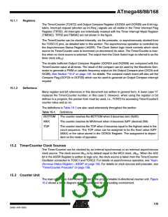
A simplified block diagram of the 8-bit Timer/Counter is shown in Figure 15-1. For the actual
placement of I/O pins, refer to ”Pinout ATmega48/88/168” on page 2. CPU accessible I/O Regis-
ters, including I/O bits and I/O pins, are shown in bold. The device-specific I/O Register and bit
locations are listed in the ”8-bit Timer/Counter Register Description” on page 149.
The PRTIM2 bit in ”Power Reduction Register - PRR” on page 40 must be written to zero to
enable Timer/Counter2 module.
Figure 15-1. 8-bit Timer/Counter Block Diagram
Count
TOVn
(Int.Req.)
Clear
Control Logic
Clock Select
Direction
clkTn
Edge
Detector
Tn
TOP
BOTTOM
( From Prescaler )
Timer/Counter
TCNTn
=
=
0
OCnA
(Int.Req.)
Waveform
Generation
OCnA
OCnB
=
OCRnA
Fixed
TOP
Value
OCnB
(Int.Req.)
Waveform
Generation
=
OCRnB
TCCRnA
TCCRnB
138
ATmega48/88/168
2545E–AVR–02/05

 MICROCHIP [ MICROCHIP ]